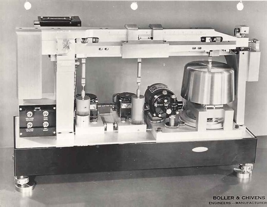
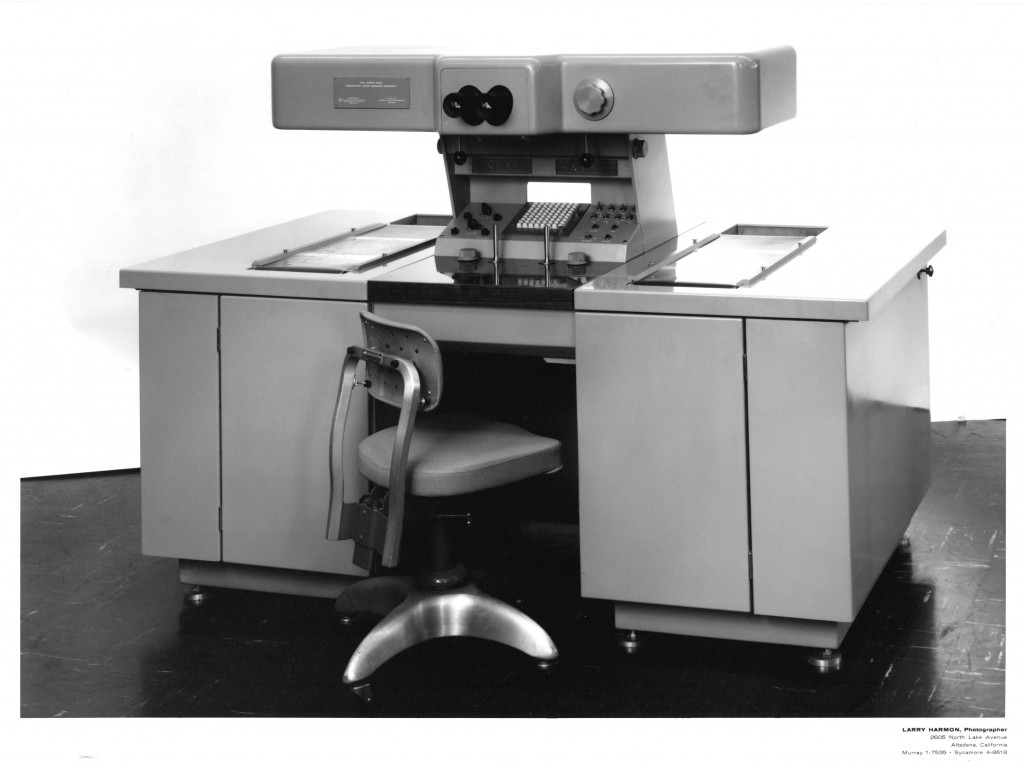
 Side Looking Radar Time-lapse Photo Comparator Console
Progressive long time-lapse photos, one on each of the left and the right desktop viewing windows were observed through the left and right monocular eyepieces.
Changes in the topography between the two photos could be observed noting such events as armament and vehicle build up, etc.
Side Looking Radar Time-lapse Photo Comparator
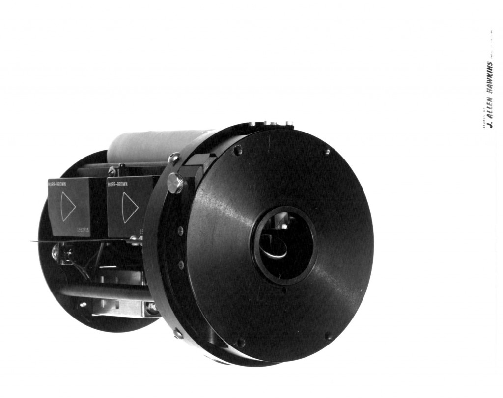
Near Infra-red Mapping Spectrometer
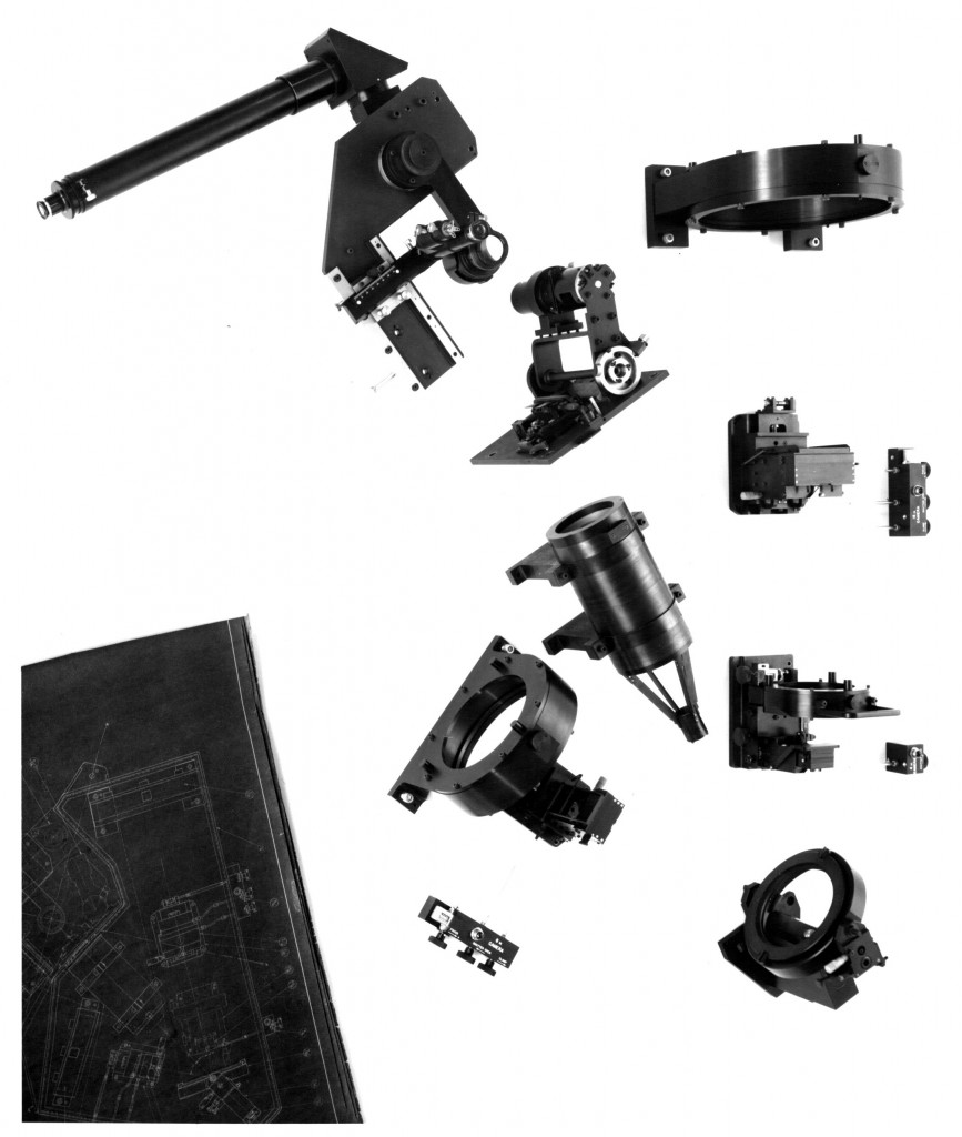
 NIMS – The optics were designed by Juan Rayces, manufactured at Perkin-Elmer Corp. Costa Mesa, and managed by Boller & Chivens for the Jet Propulsion Laboratory’s Galileo spacecraft. It was an unusual design with steep aspheric fused silica mirrors polished by Jerry Brunache, a dual blazed grating, and to hold the optics…the first material independent, temperature insensitive mounting scheme (MITI Mount).

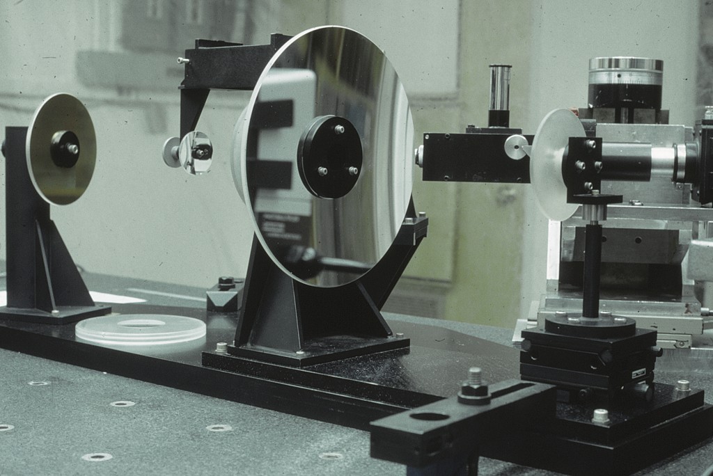
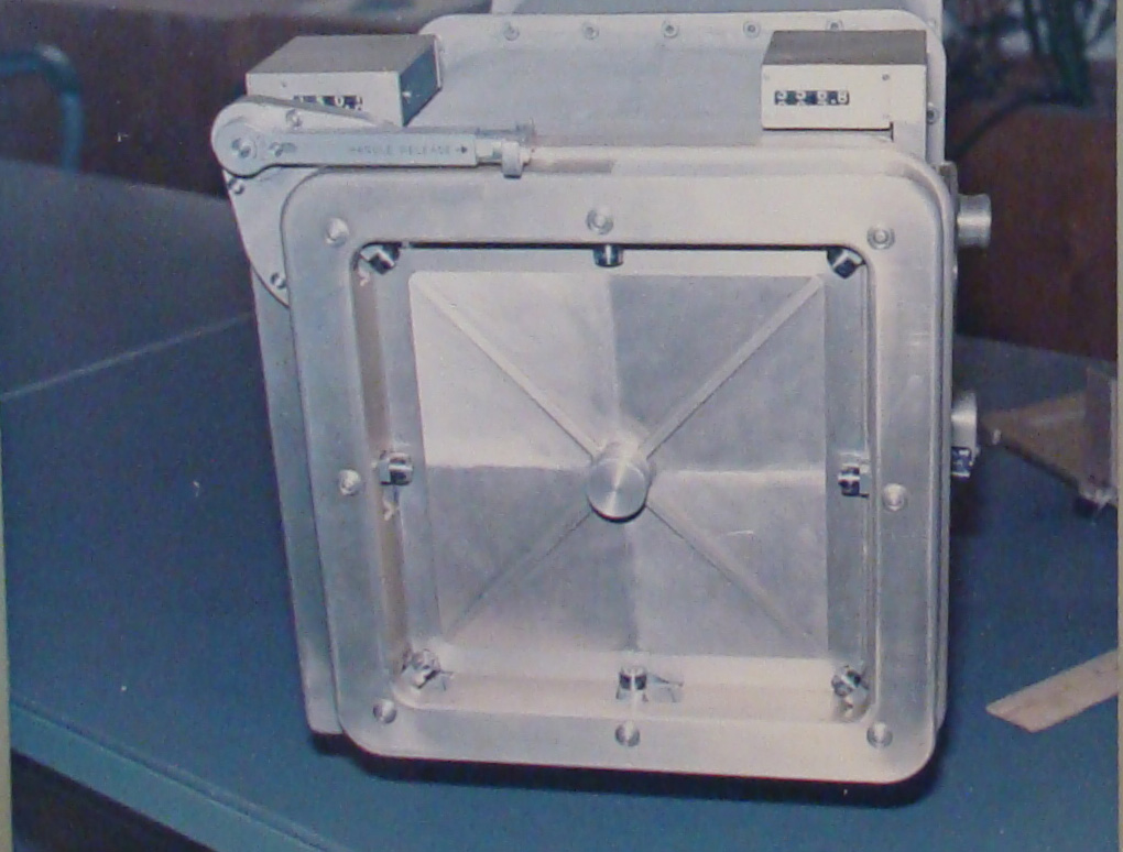
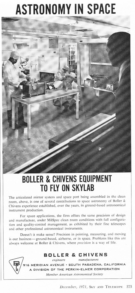
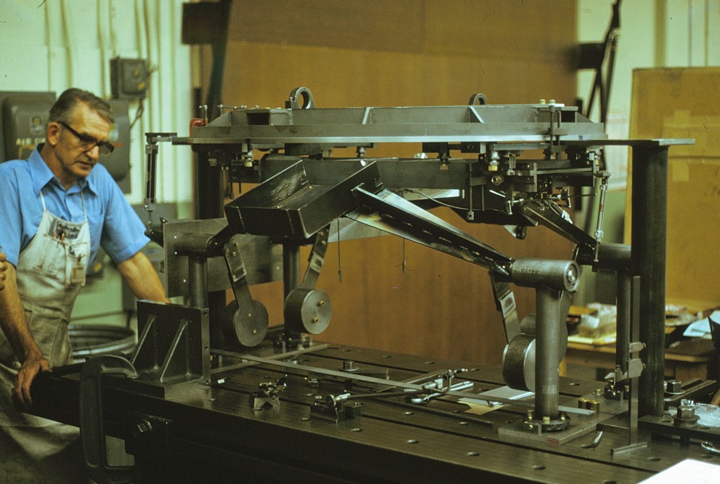
Spectrograph Camera with Articulated Mirror and Airlock System for NASA Space Orbiting Sky Laboratory
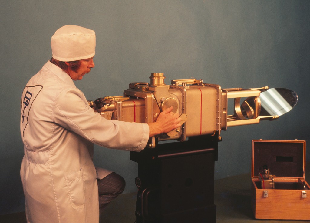 Don Daniel of Boller and Chivens demonstrating the spectrograph.
The second rectangular flange in front of Don Daniel’s hand is at the environmental boundary of the main seal area from outer space. CO2 cartridges from the main body would eject the support for the diagonal mirror in an emergency.
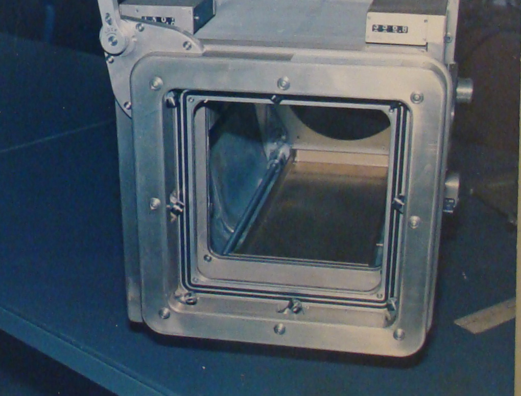 Airlock Cover removed for installing Spectrograph Camera
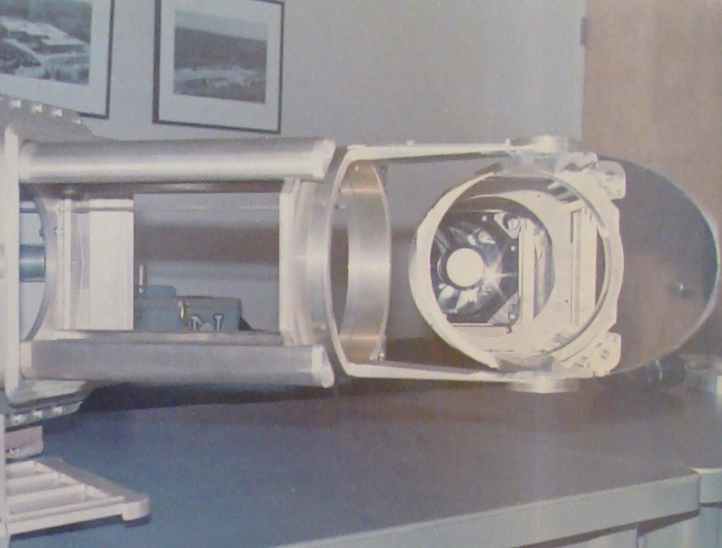 Diagonal Mirror assembly can be extended, rotated and angle changed, and retracted
For more about Skylab, visit http://en.wikipedia.org/wiki/Skylab
Photographic Zenith Tube
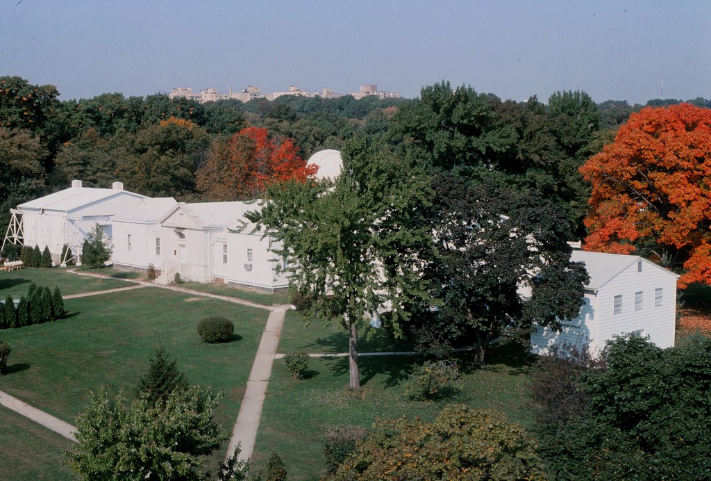 The Photographic Zenith Tube is located on the grounds of the U.S. Naval Observatory (USNO), at Number One Observatory Circle in Washington, D.C. The early 19th century buildings house the USNO, one of the worldwide national time standard observatories. At the time of the PZT installation on these grounds by Larry Averil of Boller and Chivens, it was of the latest state-of-the-art in establishing exact time through celestial observations.
The USNO shares these grounds with the U.S. Vice President’s mansion: www.whitehouse.gov/about/vp-residence
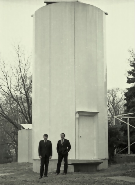 Larry Burris of Boller and Chivens pictured on right.
This structure houses the Photographic Zenith Tube, used by the US Naval Observatory to establish absolute time. It was designed by John O’Rourke of Boller and Chivens.
It is a basic telescope with a four element 26 inch diameter lens cell at the top of a 15-foot high vertical structure.
The roof on the structure opens to let starlight in. The starlight passes through the 26-inch lens cell and projects down to a 18-inch diameter mercury pool mirror at the bottom of the structure. The star image is then reflected back to the focal plane just under the 26-inch lens cell assembly.
A glass photo plate at the focal plane records the star images and a time reference is recorded at the time the image took place. The lens and photo plate are then rotated 180 degrees and the same star images are exposed on the same plate. The time is recorded again when the second image took place.
Calculations averaging both positions of the star and the averaging the time difference will give an exact celestial time which can verify and/or correct the master Naval Observatory published exact standard time.
This whole process became obsolete with the advent of atomic clocks.
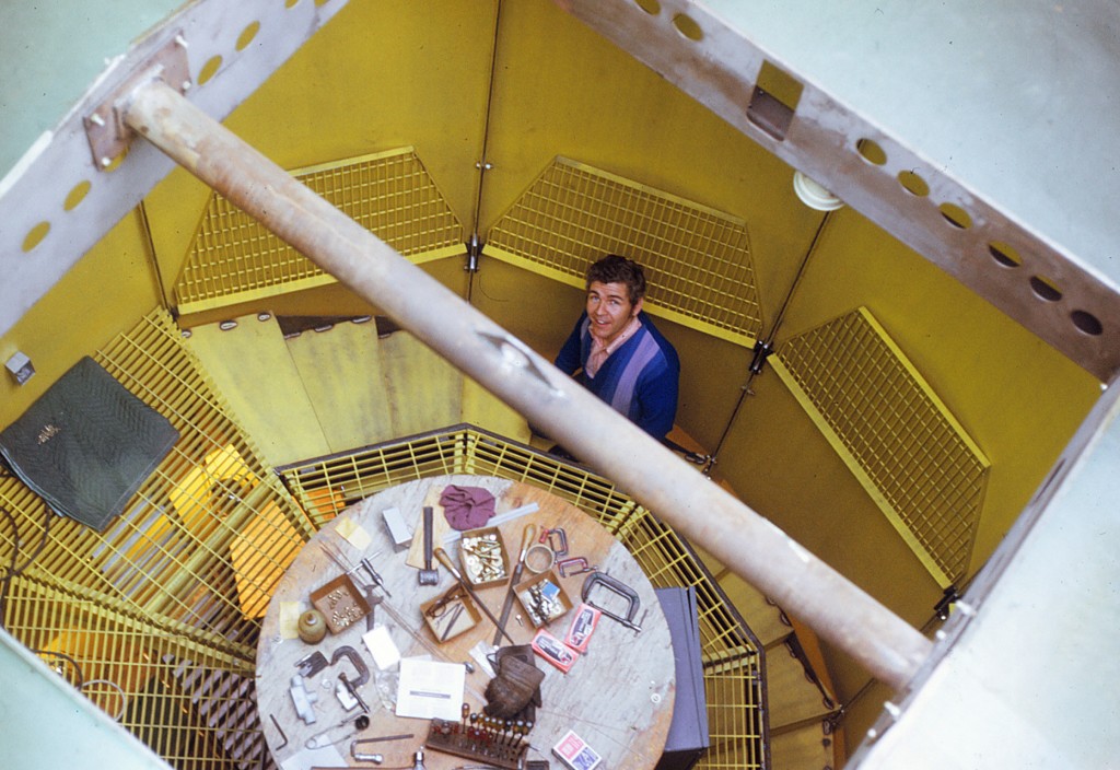 John James of Boller and Chivens working on the Zenith Tube housing
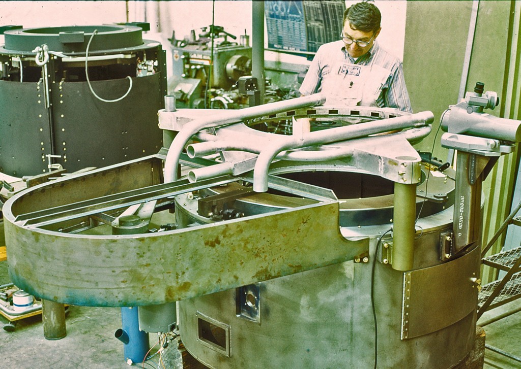 Dick Nason of Boller and Chivens working on the rotatable Camera Lens Assembly
6-Inch Warner & Swasey Meridian Circle for U.S. Naval Observatory, Washington DC
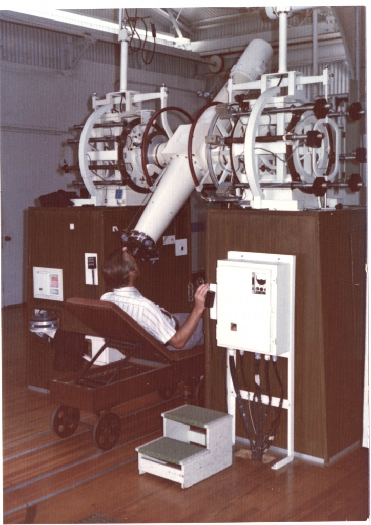 Don Winans of Boller and Chivens testing the operation of the refurbished
6-Inch Warner & Swasey Meridian Circle
Several Naval Observatory celestial instruments were hand-carried on the airplane by Don Winans of Boller and Chivens back to the plant in South Pasadena, California. The instruments were refurbished or upgraded and again hand-carried back to the U. S. Naval Observatory.
Glass Photo Plate Assembly
Boller and Chivens developed a program for generating glass photo plates for large optical encoders.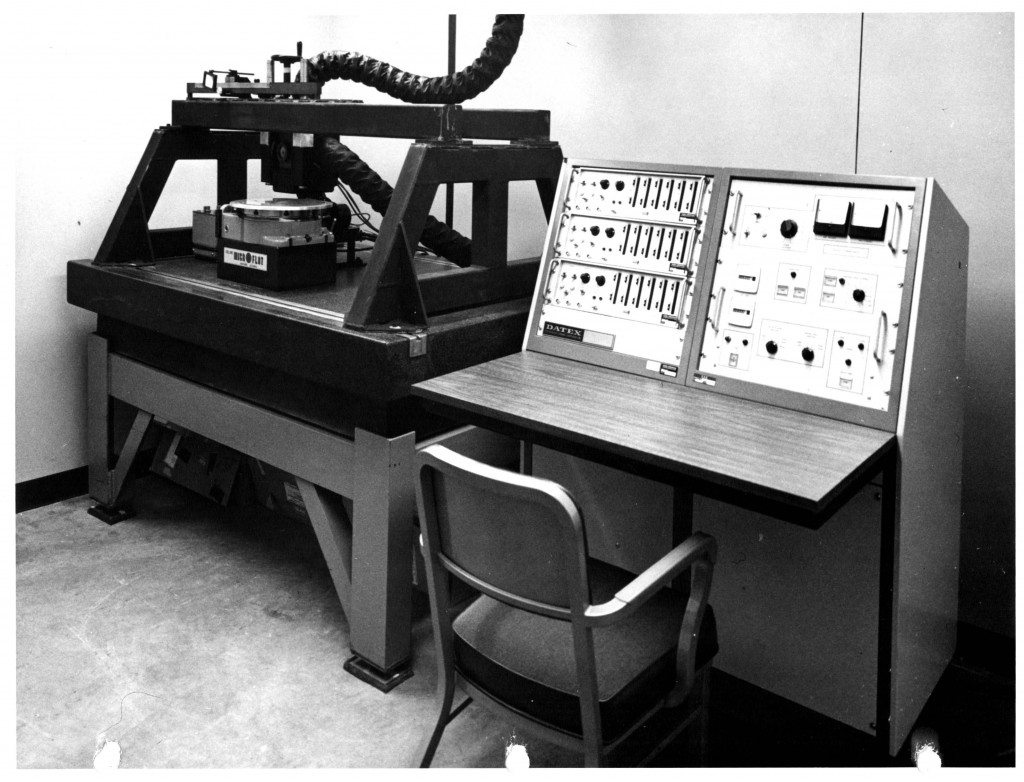
The assembly as built up :
1. Rubber Pads on Slab.
2. Steel Pads on Rubber Pads.
3. Heavy Steel Support Frame.
4. Thick Rubber Pads on frame.
5. Large Granite Surface Plate
6. Small Granite Surface Plate Bonded to Large Surface Plate
7. Precision Rotary Table operated by electronic Servo System from the control console.
8. Heavy support frame
9. Heavy cross beam
10. Optical Line Projection Assembly
11. Air Tubes scavenging projection lamp hot air away
The Operating Console.
The control panel would program the rotary table to index to many angular positions and produce.
short multiple radial lines at different radii.
With each revolution of the rotary table it was required to have absolute identical separation between
each of the hundreds of rotational lines that were being projected onto a glass photographic plate.
The temperature-controlled room was a positive clean–room environment.
X-ray Test Facility NASA – Marshall Space Flight Center, Huntsville, Alabama
Designed, manufactured, and installed by Boller and Chivens
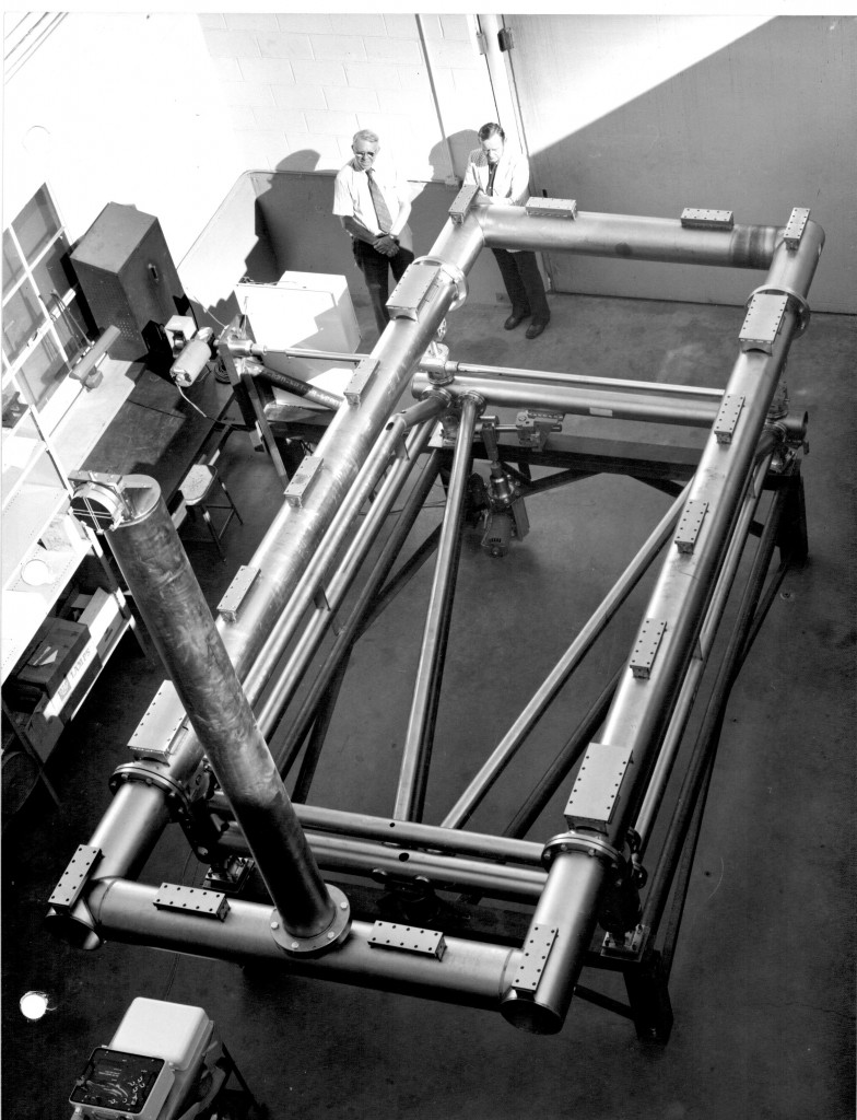 Clyde Chivens with Bliss Bushman, director of Perkin-Elmer West-coast Operations
John O’Rourke with Don Winans, Boller and Chivens designers for the High Energy Astronomy Observatory X-Ray Telescope Test-Bed.
Don Winans received the NASA Group Achievement Award for his contributions on this project.
Perkin-Elmer, Norwalk, Connecticut ground and polished the cylindrical X-Ray Telescope lenses.
A stainless steel test frame was fabricated and installed inside a large diameter surplus NASA oxygen vessel at Marshal Space Flight Center.
Connected to the vessel was a 1,600 foot long, 36-inch diameter stainless steel conduit pipe terminating at its opposite end to another stainless steel vacuum vessel containing a Boller and Chivens auto-collimating telescope combined with an alignment Laser.
Several LN2 vacuum diffusion pumps evacuated the entire large vessel, the 1,600 of conduit and the telescope vessel to a low-as-possible vacuum condition.
The vertical pipe holding an optical flat mirror and located at the front end of the test-bed is used for initial system collimation before replacing it with the actual X-Ray Telescope.
The HEO-B X-Ray Telescope was mounted on the test-bed for angular calibrations while under near- space vacuum conditions.
Electric motor drives mounted outside the vacuum chamber would rotate drive shafts through rotational vacuum seals to the azimuth and elevation angle adjustment ball screws assemblies.

The Test-Bed could be adjusted to plus or minus two degrees in both azimuth and elevation.
This photo shows the large azimuth and elevation ball-screw jacks, the custom azimuth universal
U-joint, conical ball-bearing azimuth angle rollers and the spiral flexible couplings
The four conical rollers were mounted and height adjustable at the four corners of the Test-Bed.
Pre-installed were round pipe extension tubes welded to inner wall of the large vacuum chamber for the adjustable azimuth roller assembles to be attach to.
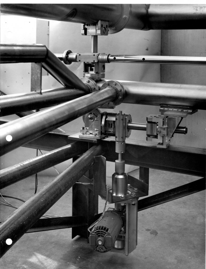
This photo, again shows the large azimuth and elevation ball-screw jacks, the custom azimuth, universal U-joint, conical ball-bearing azimuth angle rollers and the spiral flexible couplings.
It also shows the Vacuum Feed Through for the motor drive shafts through the large vessels walls.
For more information visit, http://en.wikipedia.org/wiki/X-ray_optics
LSO Landing Aid for U.S. Navy Carriers Aircraft
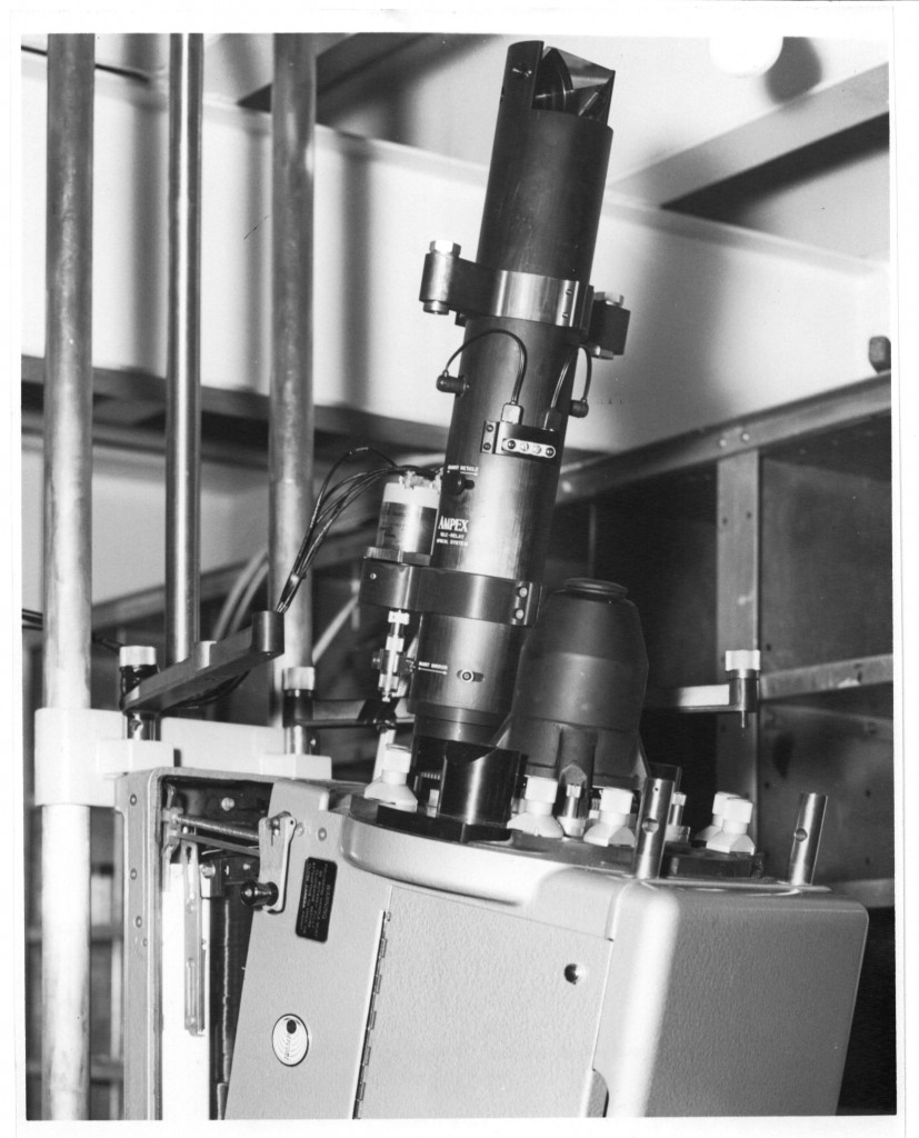 Boller and Chivens was designated as the repair depot for the Boller and Chivens USN Tele-relay optical system.
An LSO Landing Aid television camera is mounted under the flight deck of an aircraft carrier. Projecting down from the flight deck into the television camera is a Boller and Chivens Tela-relay optical system which would observe all aircraft landings on the carriers flight deck.
The tele-relay optical system is coupled to a TV camera. They are installed such that the optical flat extended just above the carriers flight deck surface looking forward to monitor aircraft landings.
A protective cap with a front-facing window covers the flat mirror protecting it from flight deck traffic.
This device augments the flight landing signal personnel that was instructing the pilot’s condition of the incoming aircrafts landing.
The TV’s video image of the landing would be transmitted to the pilot as well as many surveillances points aboard the aircraft carrier documenting every aircrafts landing.
Wind Tunnel Hydraulic Force Beam Balances for Jet Propulsion Laboratory, Pasadena, CA
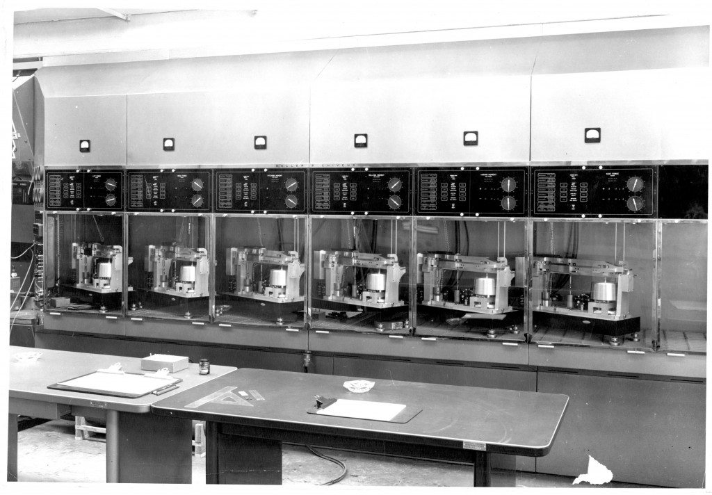 Designed and installed by Boller and Chivens for the 20-inch supersonic wind tunnel.
These balances are fully automatic in operation and read out hydraulic pressures to an accuracy of 0.1%
Six outputs of wind tunnel hydraulic pressures are interfaced with the six Boller and Chivens Beam Balance instruments. These hydraulic pressures are all applied simultaneously to the Beam Balance instruments. The pressures and moments are then monitored in the panels above the Beam Balances.
The pressure loads to be identified are Normal, Side, and Axial forces and moment loads of Pitch, Yaw, and Roll.
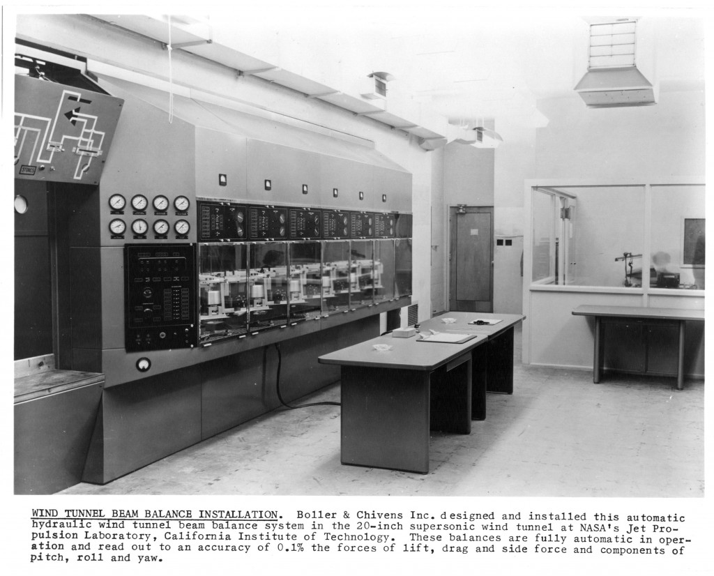 Other wind tunnel operational gauges and control panels are shown in this photo.
Photo is detail of one of the wind tunnel’s force indicating Beam Balances.

