Designed, manufactured, and installed by Boller and Chivens
 Clyde Chivens with Bliss Bushman, director of Perkin-Elmer West-coast Operations
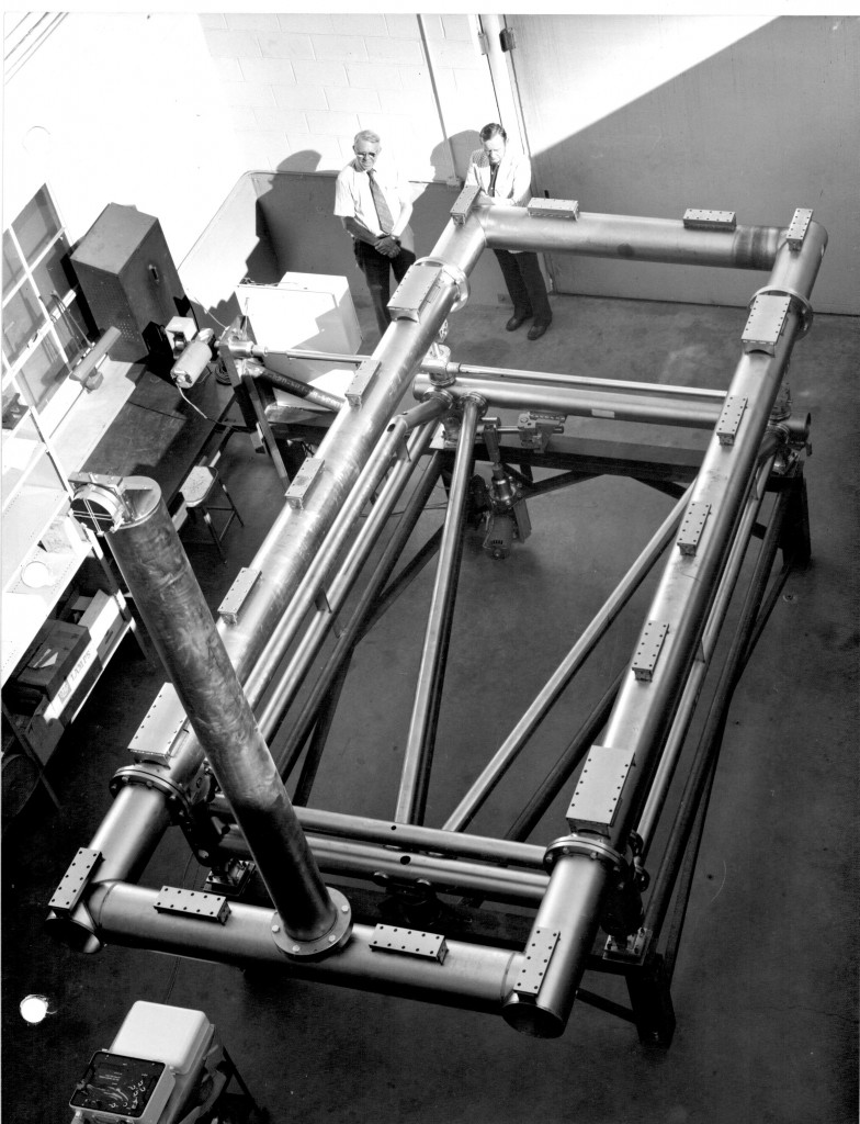
John O’Rourke with Don Winans, Boller and Chivens designers for the High Energy Astronomy Observatory X-Ray Telescope Test-Bed.
Don Winans received the NASA Group Achievement Award for his contributions on this project.
Perkin-Elmer, Norwalk, Connecticut ground and polished the cylindrical X-Ray Telescope lenses.
A stainless steel test frame was fabricated and installed inside a large diameter surplus NASA oxygen vessel at Marshal Space Flight Center.
Connected to the vessel was a 1,600 foot long, 36-inch diameter stainless steel conduit pipe terminating at its opposite end to another stainless steel vacuum vessel containing a Boller and Chivens auto-collimating telescope combined with an alignment Laser.
Several LN2 vacuum diffusion pumps evacuated the entire large vessel, the 1,600 of conduit and the telescope vessel to a low-as-possible vacuum condition.
The vertical pipe holding an optical flat mirror and located at the front end of the test-bed is used for initial system collimation before replacing it with the actual X-Ray Telescope.
The HEO-B X-Ray Telescope was mounted on the test-bed for angular calibrations while under near- space vacuum conditions.
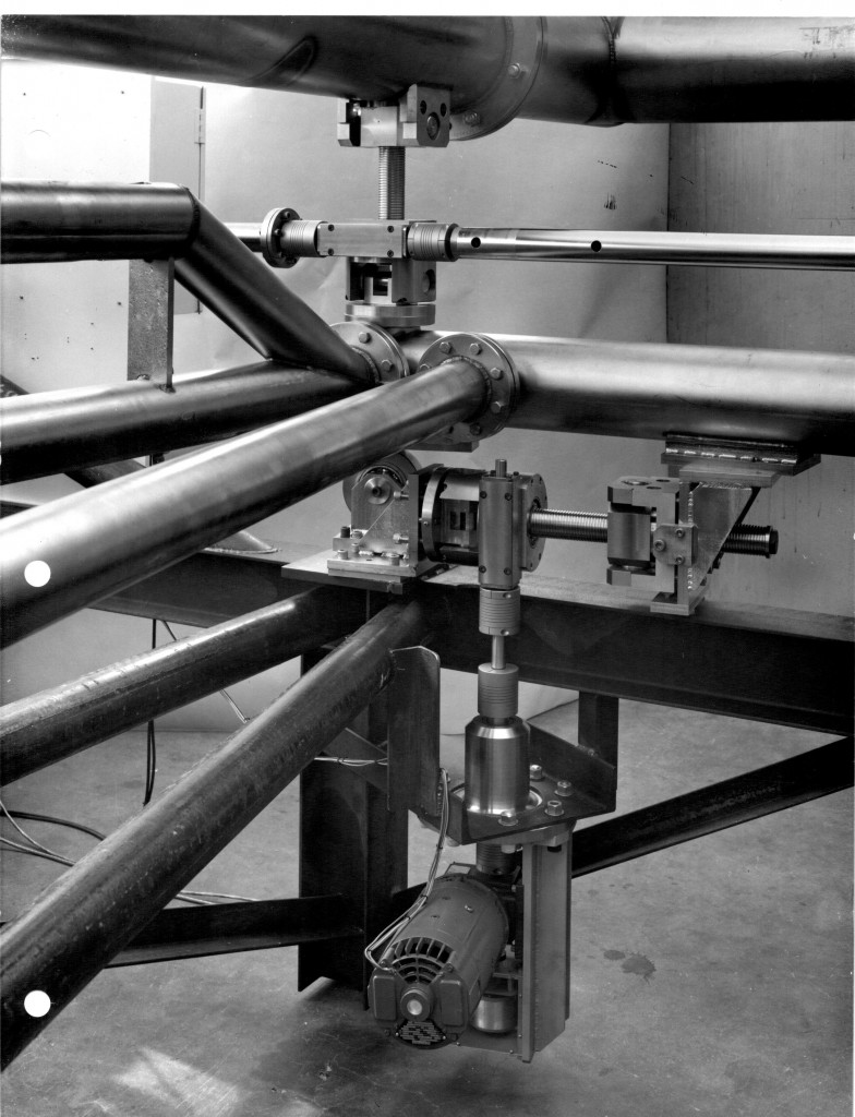
Electric motor drives mounted outside the vacuum chamber would rotate drive shafts through rotational vacuum seals to the azimuth and elevation angle adjustment ball screws assemblies.

The Test-Bed could be adjusted to plus or minus two degrees in both azimuth and elevation.
This photo shows the large azimuth and elevation ball-screw jacks, the custom azimuth universal
U-joint, conical ball-bearing azimuth angle rollers and the spiral flexible couplings
The four conical rollers were mounted and height adjustable at the four corners of the Test-Bed.
Pre-installed were round pipe extension tubes welded to inner wall of the large vacuum chamber for the adjustable azimuth roller assembles to be attach to.

This photo, again shows the large azimuth and elevation ball-screw jacks, the custom azimuth, universal U-joint, conical ball-bearing azimuth angle rollers and the spiral flexible couplings.
It also shows the Vacuum Feed Through for the motor drive shafts through the large vessels walls.
For more information visit, http://en.wikipedia.org/wiki/X-ray_optics

Comments are closed.