Spectrograph for 100 Inch Telescope for Carnegie Institute, Las Campanas Observatory, Chile
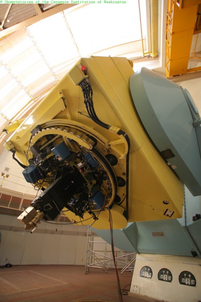
Boller and Chivens entered into a joint venture contract with L and F Industries to fabricate and complete the assembly of the 2.54 meter (100-inch) Irénée du Pont Telescope at the Las Campanas Observatory, Chile. Boller and Chivens also designed and manufactured a Spectrograph for this observatory to be used with the 100 Inch telescope.
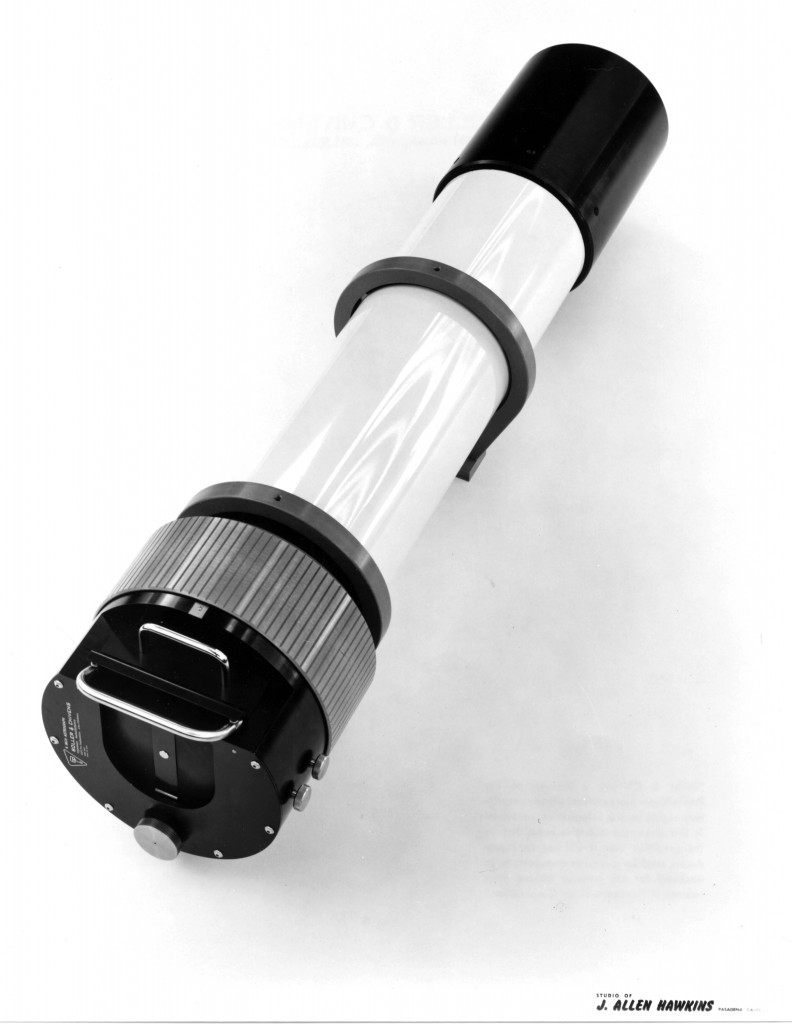
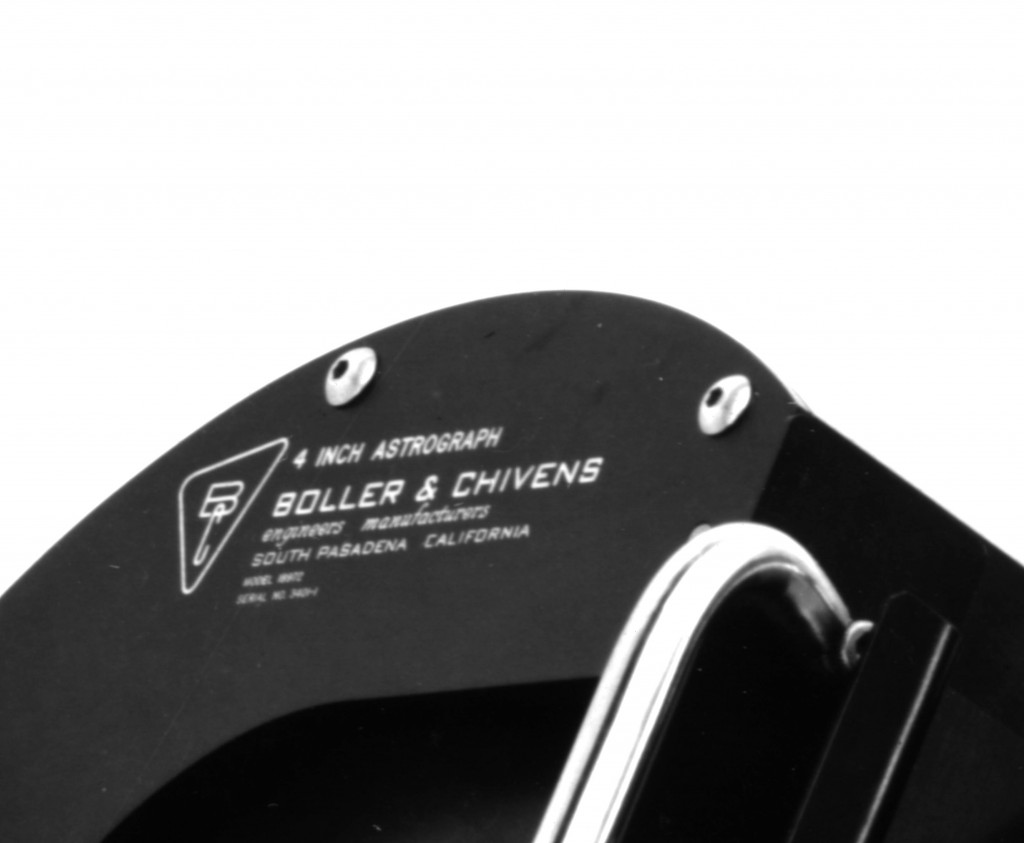
The B & C spectrograph uses a Marconi CCD mated to a Bowen Schmidt camera as the detector. When used with the 600 line/mm grating the dispersion is 1.5 Å/pixel with a wavelength coverage of 3100 Å. The spatial scale on the du Pont Telescope is 0.70 arcsec/pixel, and the maximum slit length 271 arcsec.
For more information about the support equipment on the 100 Inch telescope including the manual for this Spectrograph, visit http://www.lco.cl/telescopes-information/irenee-du-pont/telescopes-information/irenee-du-pont/instruments/
Spectrograph at Pine Bluff Observatory, University of Wisconsin
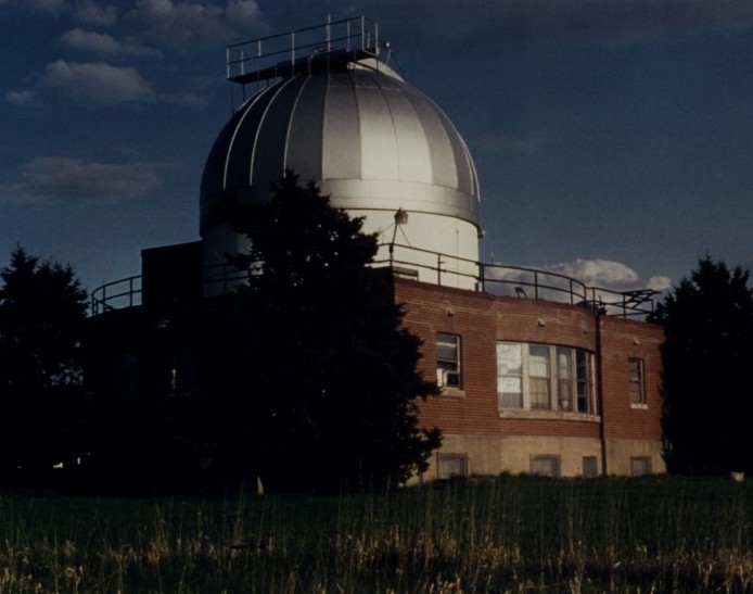
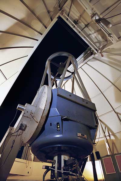 For more information regarding this spectrograph, visit the University of Wisconsin, Pine Bluff Observatory website.
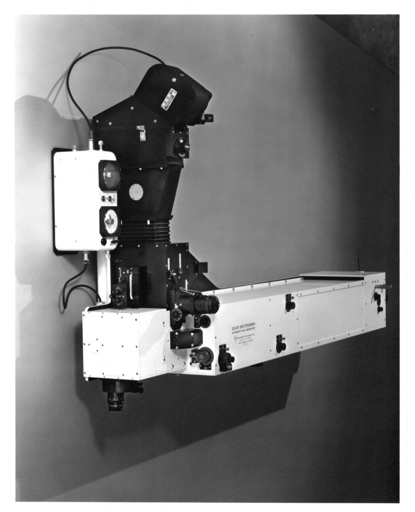
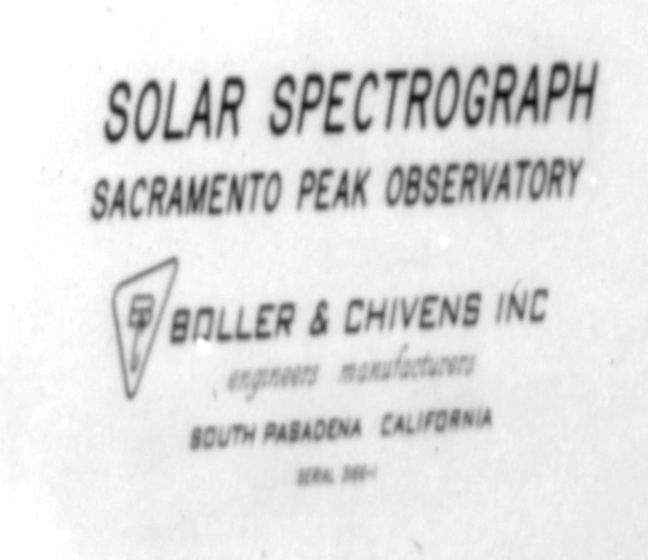
Solar Coudé Spectrograph
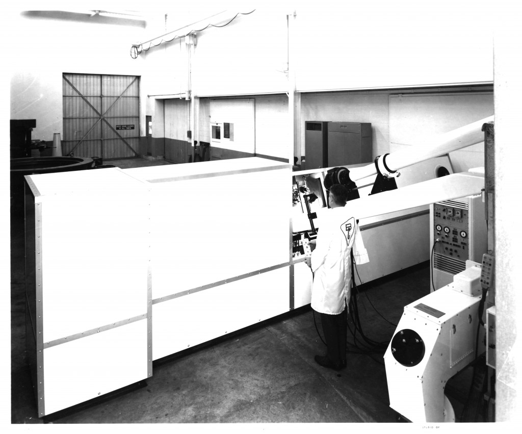 Boller and Chivens designed and manufactured the Solar Coudé Spectrograph installed at University of Hawaii.
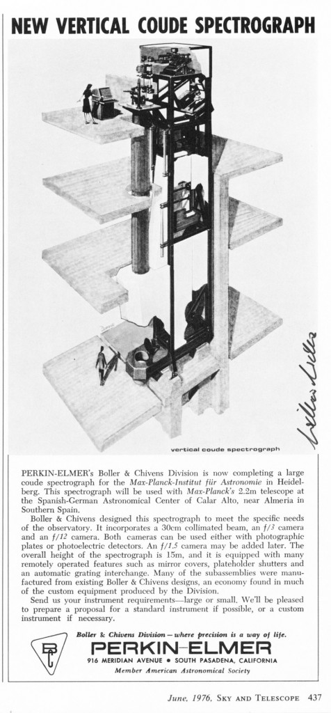
Vertical Spectrograph for Max Planck Observatory, Spain
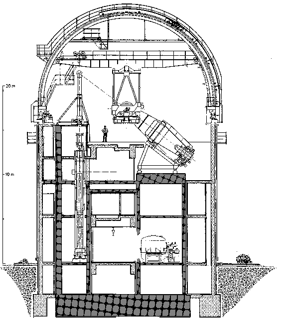 Cross section drawing of Max Planck Observatory dome. The vertical spectrograph is shown on the left side, standing more than three stories tall.
The Vertical Spectrograph was designed, manufactured, and installed by Boller and Chivens.
The Boller and Chivens assembly crew at Max Planck Observatory was Dick Nason, Ron Plate, and Larry Steimle.
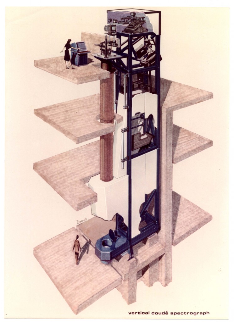 Proposal Rendering by John Demaree
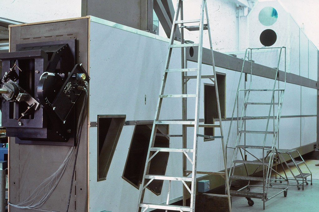 This long steel covered container houses the main assemblies for the 2.2-meter telescope Coudé spectrograph. For assembly at Boller and Chivens, the equipment was laying down horizontal. When installed at the telescope site it was to be raised up vertically with this end upright.
This end shows the grating mount assembly with the mechanism for tilting the grating.
The openings in the housing provide access to the two Schmidt cameras and a corrector lens. The f/2.5 camera nearest to the grating does require a corrector lens. The f/7camera farther down in the housing does not require a corrector lens.
Other openings provide access service to the curved focal plane cameras.
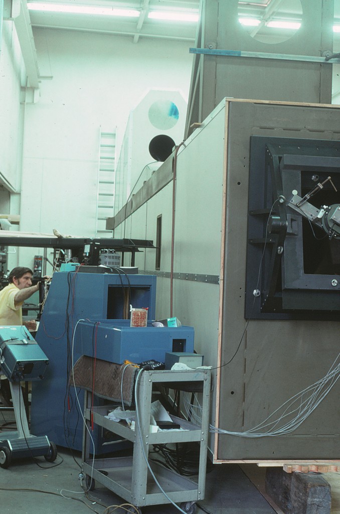 Loren Sample of Boller and Chivens pictured
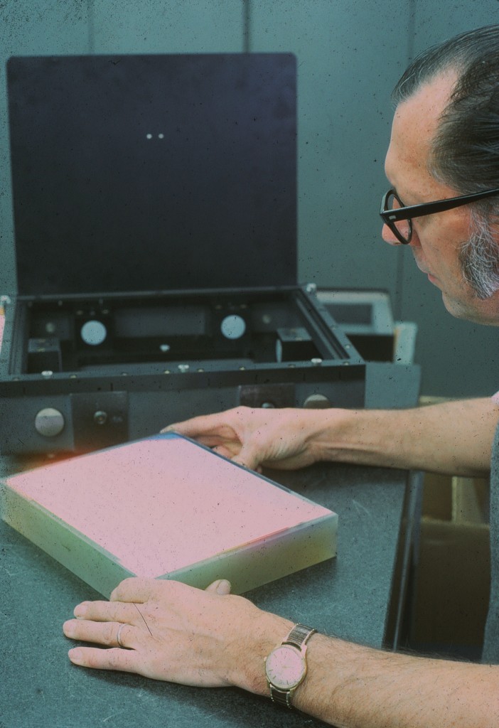 Ed Fengler of Boller and Chivens, Assembly Journeyman, handling a large optical grating
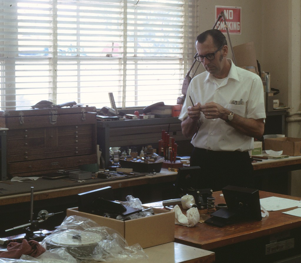 Ed Fengler of Boller and Chivens, Assembly Journeyman, assembling Spectrograph parts
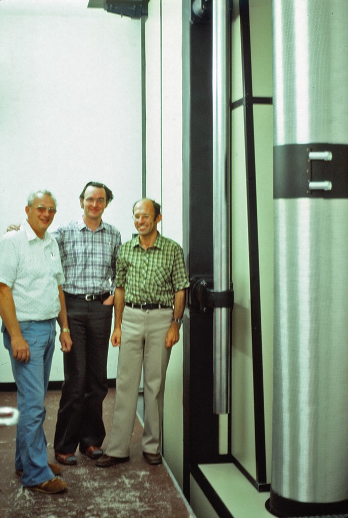 Ron Plate of Boller and Chivens on left during installation of Coudé Spectrograph.
Tube in foreground on right houses the passing Coudé focal beam.
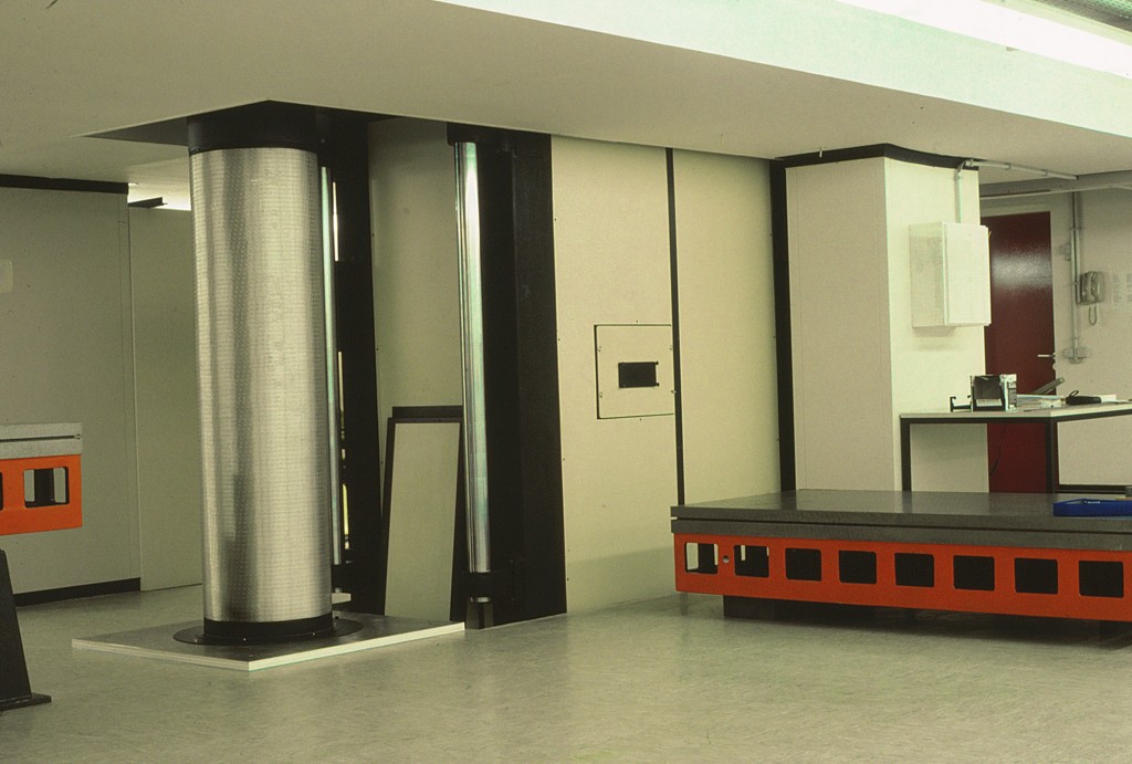 Tube shown at left houses the Coudé focal beam.
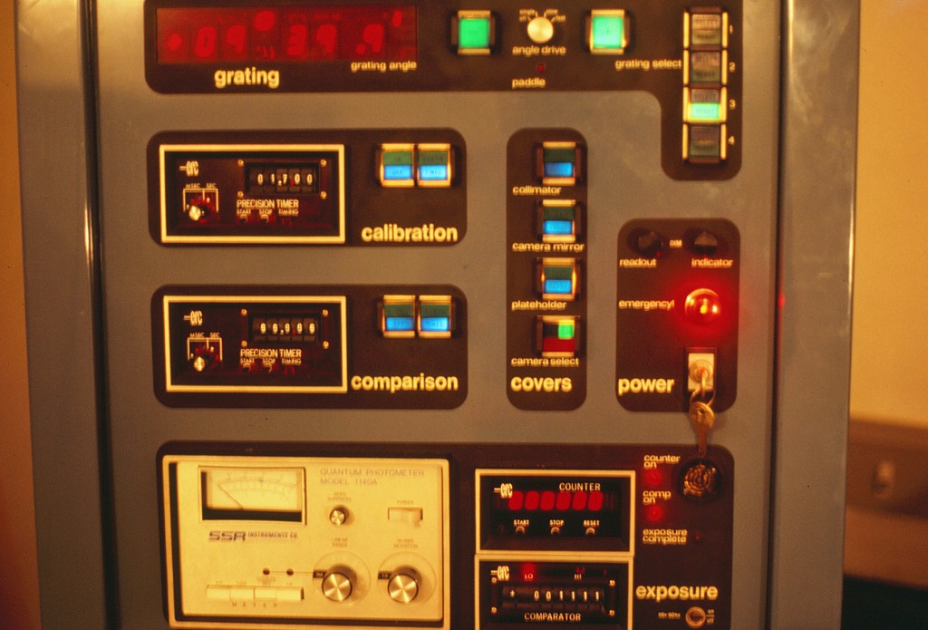 2.2-Meter Coudé Spectrograph Console by Boller and Chivens
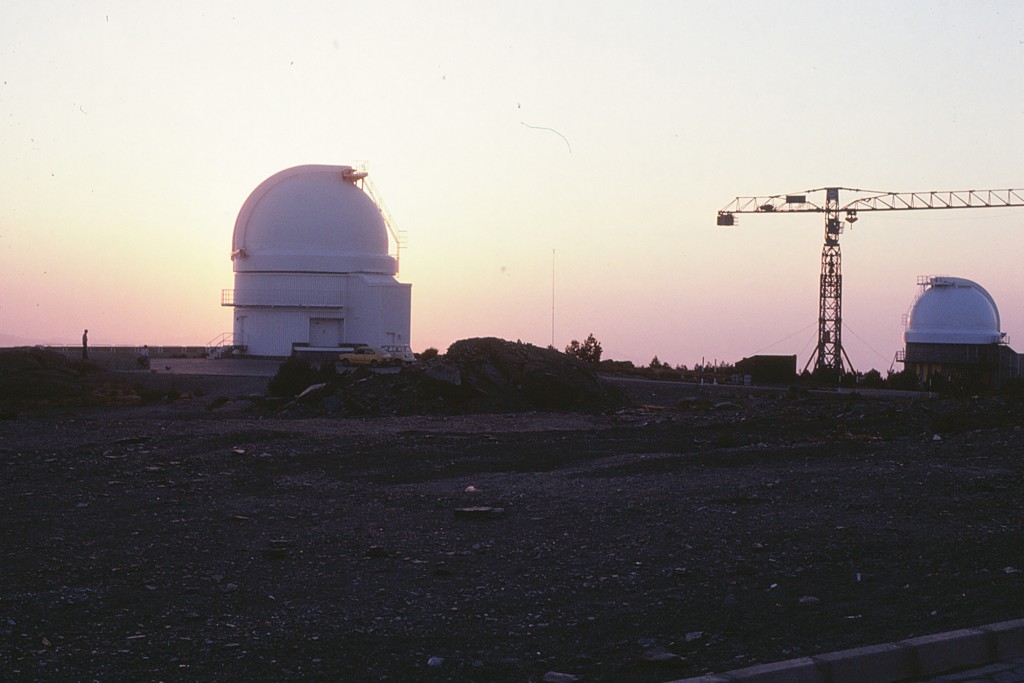 Max Planck 2.2 Meter Telescope dome
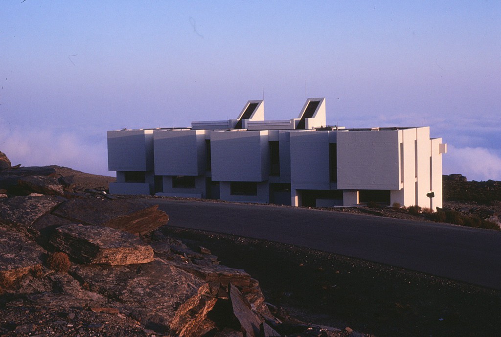 Max Planck observer apartments
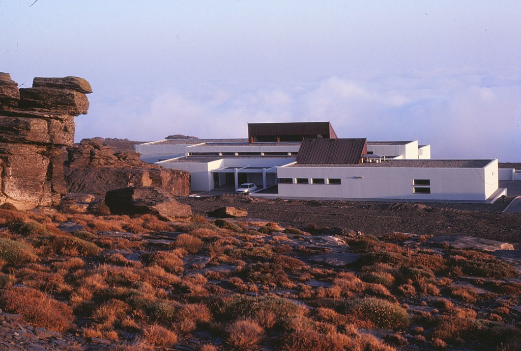 Max Planck offices
Cassegrain Focus Spectrograph for 61-inch U.S. Naval Observatory Telescope, 1968
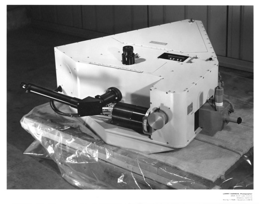
Boller and Chivens designed and manufactured
Boller and Chivens Inspection of all Telescope Primary Worm Shafts
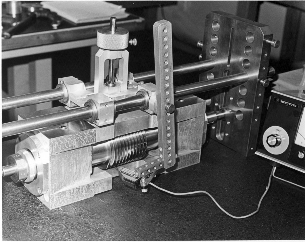
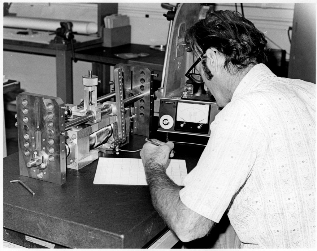 Bill De Boynton of Boller and Chivens is pictured testing a 24-inch telescope primary worm assembly.
Don Winans of Boller and Chivens designed and implemented this primary worm inspection testing device.
All Boller and Chivens telescope primary worm shafts blanks were hardened and precision ground. Each worm shaft was checked by Boller and Chivens inspection to be sure that the worm bearing diameters and the worm profile was concentric within 0.00010 TIR.
An additional inspection check was made determining that the worm helix lead tracking profile was uniform without any “drunkenness” to it.
Any “drunkenness” would show up as a blurring image when tracking an object.
All primary worm shaft ball bearings were purchased to the highest class that was available for concentricity with zero cam action.
All Boller and Chivens telescopes made “in plant” actual star observations. Each telescope would purposely be offset in its polar axis alignment with a slight base position rotation from true North.
Any stars image would then appear as a trail in the telescopes Right Ascension motion because of the telescopes misalignment.
While tracking a bright star, its image would be recorded on a glass photo plate. The stars image trail recorded on the plate should be a straight line determining the primary worm helix was linier and the mounting ball bearings did not introduced any cam action to the worm shaft.
The photo plate was then projected through an optical comparator and if the star trace was not undulating in each turn of the primary worm shaft, the telescope was determined to be tracking accurately.
The photo plate record was furnished to each telescope customer.
Inspection for worm helix uniformity “drunkenness” lead tracking profile or bearing cam action with a 0,00010 electronic Dial-indicator.
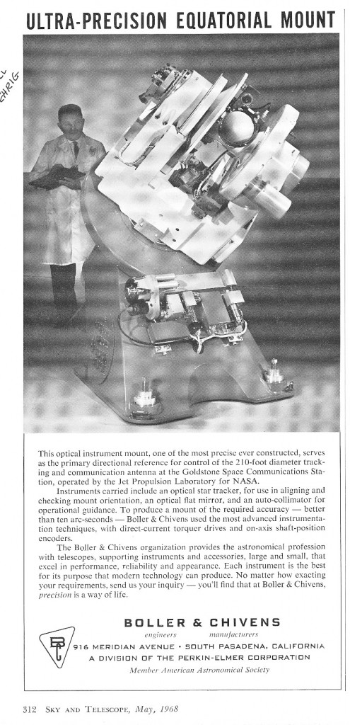
Master Equatorial Mount, Jet Propulsion Laboratory, Pasadena, California
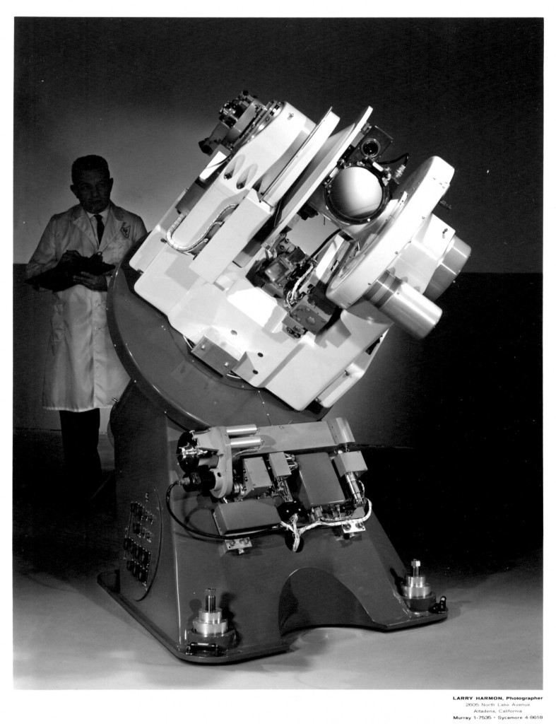 Bill Rehrig, of Boller and Chivens shown above
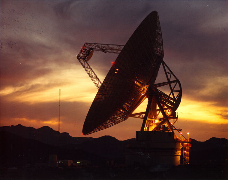
Boller and Chivens designed and manufactured three Master Equatorial Mounts for the three 70-meter radio telescopes located approximately equidistantly around the world. One is installed at Goldstone near Baker, California, one is installed at Tidbinbilla, Australia and one is installed in Robledo, Spain.
The Master Equatorial Mount is installed inside the 70-meter Radio Telescope’s dish in a dome-like housing at the intersection of where the Radio Telescope’s azimuth axis centerline crossed its elevation centerline. The fork type Master Equatorial mount would be driven to Declination and Hour Angle positions tracking in space at Right Ascension speed.
A front surface of an optical flat mirror assembly is installed on the Master Equatorial mount exactly where its polar axis crossed its declination axis and also coincides with the Radio Telescopes azimuth axis and elevation axis.
Mounted on the rear of the Radio Telescope’s dish is a 2nd optical flat mirror assembly that is spaced away from the 1st optical flat mirror assembly of the Master Equatorial Mount.
By an automatic optically auto-collimating system between the 1st and the 2nd flat mirrors, a read-out is documented exactly where the Radio Telescope dish was pointed in space.
When in operation the Master Equatorial Mount and the Radio Telescopes can be driven to a predetermined field of view. The auto-collimating system will then lock the Equatorial Mount to the Radio Telescope’s Master Equatorial Mount tracking this automatically. The reverse of this action is where the Radio Telescope is pointing at an unmapped area of interest in the sky. The Master Equatorial Mount will be driven into auto-collimation to the Radio Telescope and automatically track this interest area with positioning information being recorded.
The system’s angular repeatable accuracy was determined to be better than six arc-seconds.

