Westrex Motion Picture Editing Machines

The American phone company AT&T had created the Western Electric (Westrex) research laboratory years before to investigate technology for its clients. Engineers like Dr John Frayne and John Jacobs invented new ways of recording stereo sound that were ultimately used in nearly every Fox, MGM, Paramount, Columbia and Universal feature film.

It wasn’t surprising then that the same clients asked Westrex to create a quiet film editing device.

Through 1952 a highly experienced team at Westrex’s Hollywood division on Romaine Street worked to find a better way to edit sound films. Fred Hauser, Lewis Browder, George Crane and Herb Manley researched and built various elements of a new device and spent time with Hollywood editors asking them for feedback on proposed 35 mm editing table.

Browder was an expert in projection and applied the prism technology employed in high-speed cameras and projectors to the planned device. Hauser, a mechanical engineer, focused on the film plate and gate to guide sound picture rushes through the apparatus.

A day after Browder filed to patent a ‘film editing machine’ on April 22 1953, Crane publicly announced the the Film Editer (with two e’s). He explained to a SMPTE  meeting what they had achieved.

A film editing machine which employs continuous projection resulting in quiet operation. It accommodates standard-picture and photographic or magnetic sound film as well as composite sound-picture film. Differential synchronizing of sound and picture while running, automatic fast stop and simplified threading features in the film gates with finger-tip release materially increase operating efficiency.

Crane believed that they had ‘solved’ the Moviola’s noise problems by using:

“…continuous optical projection and the substitution of timing belt drives for gear driven mechanisms…”

In short the Editer was quiet.

The engineers used teethed belts instead of the noise making metal gear mechanisms on the Moviola. The Westrex machine was also much simpler to thread , yet not easy to slip sync.

“…placing the film in the film trap automatically locks the film to the drive sprocket so that the position of the film cannot be lost inadvertently.” 

Browder had enhanced the previous work of engineers Bill Harrison and Franz Ehrenhaft in prism projection. The Editer’s rotating 12-sided prism enabled smooth viewing on the editor’s screen as well as enabling it to project images to an adjacent wall for a director’s screening.

Westrex commissioned a South Pasadena based manufacturing specialist, Boller and Chivens to build the units. Boller and Chivens had previously made precision equipment like wind tunnel strain gauges and film camera viewfinders.

Boller and Chivens built a special motor for handling the film and sound rushes at a variety of speeds and then constructed the iconic aluminum console that could be operated standing up, or sitting down.

A young Anthony Tony Buckley A.M. used a Westrex on location to edit Michael Powell’s adaptation of Norman Lindsay’s novel, Age of Consent. Buckley recalled in his autobiography, Behind a Velvet Light Trap.

“Despite having the windows and doors open, the film began sticking to itself. Worse, the mirrors on the Westrex Editer began to deteriorate, but the final straw came when I and the film I was cutting, were pulled into the machine. The moisture adhering to the celluloid was unbelievable. 

An air-conditioner was requested and much to our surprise an air-conditioner arrived. (We) were soon working in the comparative lap of luxury, much to the envy of our fellow crew members.” 

Westrex sold more than 50 units and won a technical merit Academy Award®.

for the design and construction of a new film editing machine”

The company was asked to make an Editer to accommodate the editing of the Todd-AO 70 mm based musical South Pacific. The machine was modified to accommodate two 35 mm magnetic films, each containing six stereophonic sound tracks.

Thanks to John Buck for providing the above text from his book Timeline Digital

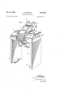
Westrex Editer – The patent papers

Save

Dames and Moore, Incorporated


Boller and Chivens designed and manufactured several soil testing instruments for Dames and Moore. This instrument would apply compression loads to soil samples for analysis.      Boller and Chivens made several of these instruments.

This instrument was a Direct Shear Apparatus that would apply soil shear loads to soil samples for analysis.

Helipot Precision Potentiometer Division, a subsidiary of A.O. Beckman Corporation


Boller & Chivens designed, manufactured and assembled all of Helipot’s continuous coil-winding machines. Each winding machine continuously wound a special resistance wire around an insulated copper core wire. The helical winding of the wire spacing was controlled to very close tolerances.
In a continuous operation the core wire came off a drum running vertically through a wire straightening set of rollers and then over a selectable geared wire speed shive that controlled the core wire traveling speed.
A winding head assembly contained the resistance wires spool when spinning at high speed, and wound the resistance wire around the traveling copper core wire.
The resistance wire wound core wire passed down around a large idler pulley at the lower end of the column. It then progress up thru a pre-heater box and then through a Formex applicator assembly that applied a coating to three sides of the assembled wire.   The Formex applicator was designed so that it could be adjusted to keep an inside area of the final coiling uncoated for electrical continuity when at the last stage was coiled.  The assembled wire continued traveling up through a temperature controlled parabolic cal-rod reflector-baking oven.
The final operation of the coil-winding machine was for the assembled wire being accurately formed into a coil that would be the exact diameter to fit into the Helipot housings. The continuous coils were then cut to length and assembled into Helipot 10 turn potentiometers.
Many of these continuous coil-winding machines were manufactured for Helipot.

Helipot Ratio Selector Measuring Device
This was an instrument that would measure inches of Helipot coil windings coming off the continuous winding machines. It would check that the coils had the proper resistance via the wire spacing on the core wire. The instrument would adjust the speed of the core wire passing the helix placement position where the resistance was applied to the core wire. Gear ratios could be varied in the driving wheel speed.

This is a later model for Helipot’s continuous coil-winding machines with several updates.   The force required in pulling the core wire through the core wire-straightening device would cause the wire to creep on the diving wheel. Because of this creeping, the winding head would apply irregular helical windings on the core wire.
The core wire-straightening device was moved away from of the main column assembly and positioned adjacent to it.
A motor driven friction driver would pull the core wire off the supply drum enabled the straightening set of rollers to apply additional pressure.
A free loop of wire of core wire was created between the wire straightener and the speed controlled core wire diving wheel.                                                                                                              The tension in this loop was then controlled by swing roller arm connected to a rheostat controlling the core wire driving motor speed.
The large idler wheel was attached to a pivoting arm at the bottom of the column.
A sliding a weight could be moved across the arm to adjust the tension of the wire in this area.
The coiling mechanism was improved upon and additional controls added on the column.

Helipot Winding Lathe

Boller & Chivens designed, manufactured and assembled Helipot’s Winding Lathes.              Each winding lathe wound a special resistance wire around an insulated length of copper core wire.
The helical winding of the wire spacing was controlled to very close tolerances. The design used a modified a South Bend lathe as the base for the winding machine. At the headstock outboard end, gearing was added to drive a variable speed Grahm Drive unit coupled with a custom Boller and Chivens differential. This new gearing would drive the standard South Bend quick-change lead screw drive at variable rates. In addition to driving the lead screw drive, the gearing from the headstock end drove a rotating drive shaft that extended to the tailstock end through the center of the lath bed ways.
Gearing from the tailstock end of this driveshaft, drove a rotating tailstock assembly. A copper core wire was stretched between the Jacob’s chucks located at each end of the lathe.           Located on top of the lathe’s traveling carriage was a resistance wire spool assembly and wire guiding the application of the resistance wire winding on the core wire.
When the lathe was in operation, the moving carriage assembly would travel down the lathe bed winding the resistance wire around the core wire. The lead of the resistance could be varied to meet different design conditions.
These accurately wound wire armatures would be assembled into a Helipot product line.

Many of these winding lathes were manufactured for Helipot.
Helipot Winding Lathe Traveling Carriage

All the linear core wire-winding operation was controlled from this carriage assembly.

Oil Sampling Test Assembly for Schlumberger Well Service Company


Schlumberger Well Service Company contracted Boller and Chivens to manufacture a predesigned oil sampling test assembly.  The assembly would be lowered down to predetermined elevations in oil wells that were presently being drilled. At a predetermined depth a pair of shoes in the center of the test assembly would expand out to the drilled diameter and seal the area from any local contamination that area. A signal would then be sent down to fire two projectiles to break up the local strata. Well pressure would then push gaseous and/or liquid samples into storage cylinders located at each end of the test assembly. The shoes would then be retracted and the assembly would then be brought back up to the surface for analyzing the retrieved contents.

Over a period of several years, Boller & Chivens manufactured over 50 of these oil-sampling assemblies.

Pictured below is a close-up of the rubber sealing shoe with the projectile ports in the center.                                                                                                                

Plating Machine


Boller and Chivens entered into a classified contract to develop and manufacture equipment for handling military ordinance raw parts in their final cadmium plating processes.
The parts consisted of an inner pair of steel half diameter spherical serrated shells. Two half shells would be then filled explosive material and bonded together. The assembled shells would then receive a pair of sheet metal formed covers that would be crimped together forming a tennis ball size Bomb-let.
Hundreds of these small Bomb-lets would be deployed from a bomber flying over enemy implements.
As the Bomb-lets fell the fins on their sheet metal covers would cause them to spin and arm them. When striking the ground they would bounce and detonate spaying shrapnel over a fairly large area. They were very efficient for their purpose.
The contract required the plating lie to be completely automated because of the large quantities involved that would be produced.
The finished separate type metal parts would be stored in automatic round carousel type accumulators as they were machined.
The plating line consisted of a line of large chemical tanks cleaning, etching and cadmium plating solutions. Two computer controlled overhead cranes serviced the plating line.
Boller and Chivens developed a large bridge type frame that held a series rotating wheels mounted on a long rotating copper axle. Each of the wheels held several hundred nonmetallic receiver clips. Each clip would hold one type of part to be plated.
As the series of wheels rotated, one side where already parts had been plated, the clips would open and the plated part would be transported to another automatic round carousel type accumulators.
Simultaneously on the opposite side of the wheel when the open clips arrived, non-plated parts would be fed to the wheels empty clips.
When all the wheels were filled the crane would pick up the frame and enter it into the plating line operation. Then the crane would bring back a new wheel of plated parts to unload and be reloaded.

Automated Immunoelectrophoresis Machine

The Automated Immunoelectrophoresis Machine was designed, manufactured and installed by Boller and Chivens.
One of John O’Rourke’s last jobs with Boller and Chivens before the merger with Applied Optics Division in 1980, was a very interesting job for the government of Japan. An expert in immunoelectrophoresis at USC Medical Center talked the Japanese government into funding the design and manufacture of an automated electrophoresis machine. The General Manager of Boller and Chivens, Larry Burris, was a USC alumni and made the contact. The machine had everything, X-Y traversing mechanisms, Pipetting needles, digital camera on the traverse head, fiberoptic lights, electrophoresis trays and electrophoresis power supply.

Immunoelectrophoresis is a general name for a number of biochemical methods for separation and characterization of proteins based on electrophoresis and reaction with antibodies. All variants of immunoelectrophoresis require immunoglobulins, also known as antibodies reacting with the proteins to be separated or characterized.

After  the machine was finished the Japanese took it back to Japan to write the software for analyzing the test results. Problems developed with the software and the funding. The project was dropped. The machine was purchased by USC and returned to Los Angeles. Bill DeBoynton, of Boller and Chivens Applied Optics Division, helped set it up at USC Medical Center.

Aerial Mapping Camera Calibrator for Hill Air Force Base

The Aerial Mapping Camera Calibrator was designed, manufactured, and installed by Boller and Chivens.Larry Steimle of Boller and Chivens with Hill AFB representative with 121 Collimator Aerial Mapping Camera Calibrator

At the console operating 121 Collimator Aerial Mapping Camera Calibrator setup.
In foreground is the camera mounting area with the theodolite collimator
aligning assembly in place. The 121 collimators, each projecting a cross-hair
at known angles +/- 2.0 arc second absolute, and was stable to +/- 1.0 arc second.

Underside looking up  showing the 121 Collimator Distortion Array setup.

This is a photo of the Aerial Mapping Camera Calibrator base during construction.

Offset Guider

Camera with Dual Offset Guider

A 16cm by 16cm camera with two guiding eyepieces and manual shutter designed and manufactured by Boller and Chivens.

Twin Astrograph

Cy Denny of Boller and Chivens Project Engineer shown in above advertisement.