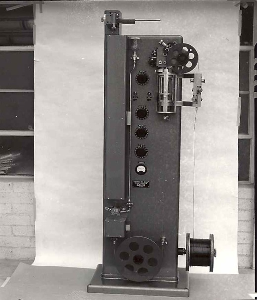
Boller & Chivens designed, manufactured and assembled all of Helipot’s continuous coil-winding machines. Each winding machine continuously wound a special resistance wire around an insulated copper core wire. The helical winding of the wire spacing was controlled to very close tolerances.
In a continuous operation the core wire came off a drum running vertically through a wire straightening set of rollers and then over a selectable geared wire speed shive that controlled the core wire traveling speed.
A winding head assembly contained the resistance wires spool when spinning at high speed, and wound the resistance wire around the traveling copper core wire.
The resistance wire wound core wire passed down around a large idler pulley at the lower end of the column. It then progress up thru a pre-heater box and then through a Formex applicator assembly that applied a coating to three sides of the assembled wire. The Formex applicator was designed so that it could be adjusted to keep an inside area of the final coiling uncoated for electrical continuity when at the last stage was coiled. The assembled wire continued traveling up through a temperature controlled parabolic cal-rod reflector-baking oven.
The final operation of the coil-winding machine was for the assembled wire being accurately formed into a coil that would be the exact diameter to fit into the Helipot housings. The continuous coils were then cut to length and assembled into Helipot 10 turn potentiometers.
Many of these continuous coil-winding machines were manufactured for Helipot.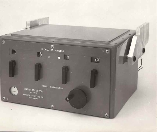
Helipot Ratio Selector Measuring Device
This was an instrument that would measure inches of Helipot coil windings coming off the continuous winding machines. It would check that the coils had the proper resistance via the wire spacing on the core wire. The instrument would adjust the speed of the core wire passing the helix placement position where the resistance was applied to the core wire. Gear ratios could be varied in the driving wheel speed.
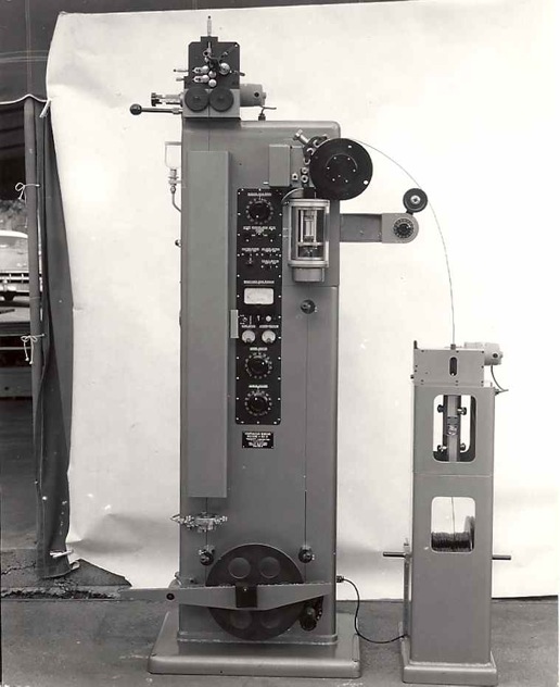 This is a later model for Helipot’s continuous coil-winding machines with several updates. The force required in pulling the core wire through the core wire-straightening device would cause the wire to creep on the diving wheel. Because of this creeping, the winding head would apply irregular helical windings on the core wire.
The core wire-straightening device was moved away from of the main column assembly and positioned adjacent to it.
A motor driven friction driver would pull the core wire off the supply drum enabled the straightening set of rollers to apply additional pressure.
A free loop of wire of core wire was created between the wire straightener and the speed controlled core wire diving wheel. The tension in this loop was then controlled by swing roller arm connected to a rheostat controlling the core wire driving motor speed.
The large idler wheel was attached to a pivoting arm at the bottom of the column.
A sliding a weight could be moved across the arm to adjust the tension of the wire in this area.
The coiling mechanism was improved upon and additional controls added on the column.
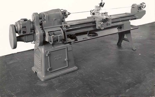
Boller & Chivens designed, manufactured and assembled Helipot’s Winding Lathes. Each winding lathe wound a special resistance wire around an insulated length of copper core wire.
The helical winding of the wire spacing was controlled to very close tolerances. The design used a modified a South Bend lathe as the base for the winding machine. At the headstock outboard end, gearing was added to drive a variable speed Grahm Drive unit coupled with a custom Boller and Chivens differential. This new gearing would drive the standard South Bend quick-change lead screw drive at variable rates. In addition to driving the lead screw drive, the gearing from the headstock end drove a rotating drive shaft that extended to the tailstock end through the center of the lath bed ways.
Gearing from the tailstock end of this driveshaft, drove a rotating tailstock assembly. A copper core wire was stretched between the Jacob’s chucks located at each end of the lathe. Located on top of the lathe’s traveling carriage was a resistance wire spool assembly and wire guiding the application of the resistance wire winding on the core wire.
When the lathe was in operation, the moving carriage assembly would travel down the lathe bed winding the resistance wire around the core wire. The lead of the resistance could be varied to meet different design conditions.
These accurately wound wire armatures would be assembled into a Helipot product line.
Many of these winding lathes were manufactured for Helipot.
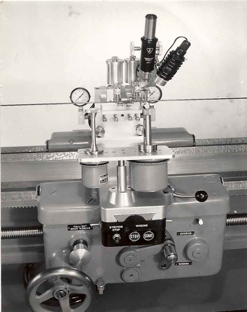 Helipot Winding Lathe Traveling Carriage
All the linear core wire-winding operation was controlled from this carriage assembly.

Comments are closed.