Boller and Chivens entered into its first successful of many Joint Ventures (with L & F Industries) in manufacturing large telescopes with the 61 Inch (1.55 meter) telescope for the U.S. Naval Observatory.
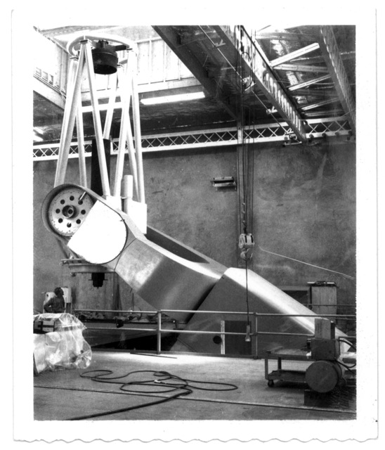 Declination axle alignment at L & F Industries’ new assembly building
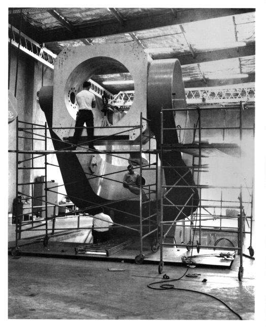 Installation of upper tube Serrurier trusses and secondary mirror support ring.
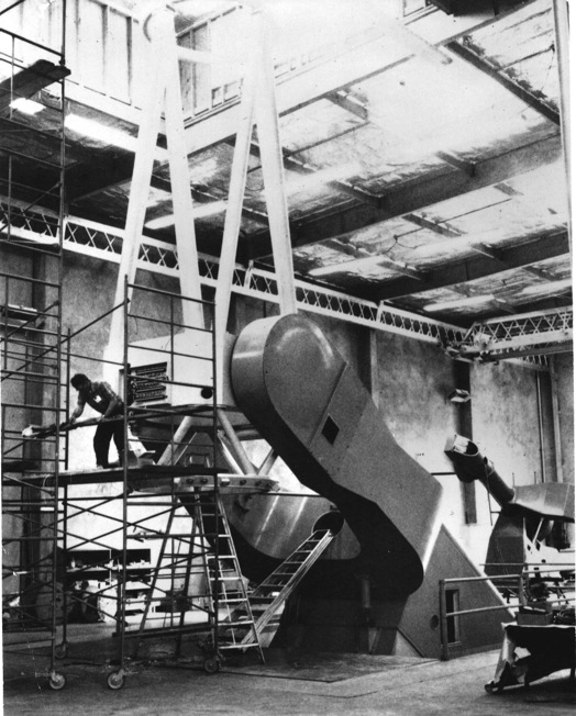 Final assembly showing lower tube Serrurier trusses and wiring of the telescope.
(in the background: the 40 Inch telescope for Siding Spring, Australia)
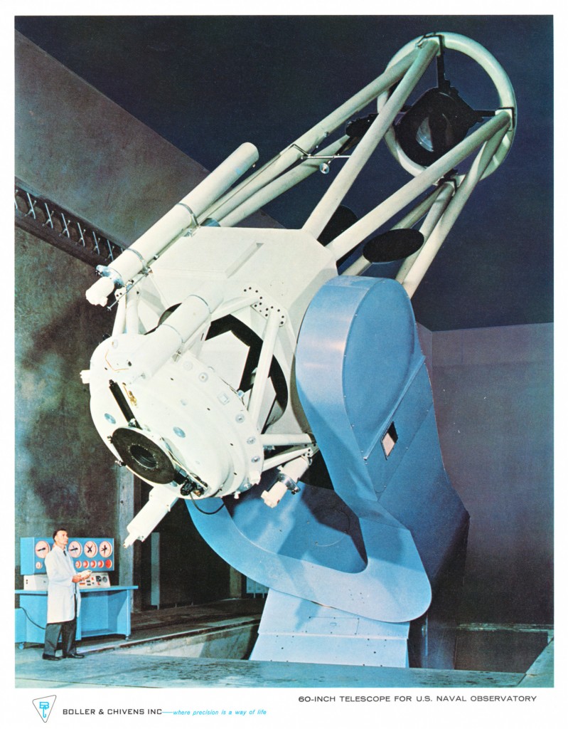 Harry Boller at the console showing the operation of the 61 Inch telescope using the remote control paddle.
The telescope was now complete and ready to be disassembled and transported to the U.S. Naval site in Flagstaff, Arizona. Boller and Chivens and L & F Industries personnel reassembled the telescope and aided in its final checkout tests.
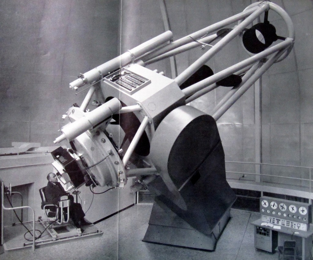 Sky & Telescope, April 1964. pp. 232-3, Official U.S. Navy photograph. K.A. Strand pictured.
This was an astrometric telescope designed to be stable and with a long focal length. It’s purpose was to do precise measurements of stellar parallax and thus determine distances to “nearby” stars. It had a 15 meter focal length paraboloidal primary (F/10) and a flat secondary mirror.
The U. S. Naval 61 inch (1.55 meter) telescope was first Boller and Chivens telescope implementing a floating polar axle oil pad bearing system. See two photos in the accompanying link to Sky and Telescope Magazine Article. All future Boller and Chivens telescopes larger than 60 Inch (1.5 meters) were equipped with oil pad bearing systems. The oil pad system bearings create frictionless rotation of the polar axle that is supporting the total mass weight of the telescope.
A large round accurately ground cylindrical drum is attached to the upper end of the polar axle/fork assembly. This drum is near is near the center-of-gravity of the moving telescope mass.
Two cylindrical shaped oil pad assemblies are angularly located, one on each side of the polar axle at approximately 30 degrees on each side of the telescopes centerline.
An accurately ground flat surface radically spans the polar axle drums lower side. A third flat oil pad is located such that it bears on the drums flat surface.
These two cylindrical shaped radial oil pads plus the third flat axial oil pad support the total weight of the telescope mass.
Finally, located at the lower end of the polar axle, is a precision radial roller bearing. This roller bearing, the two radial controlling oil pads and axial thrust oil pad bearing keep the telescope pointing accurately to its proper celestial pole position.
In operation, a oil pumping system supplies each oil pad with enough pressure the float the telescope mass. When each of the three oil pads achieves a separation away from the surfaces on the fork drum from 0.002 inch to 0.004 inch, the telescope can safely be driven at tracking speeds to full slewing speeds.
Each oil bad bearing surfaces are constructed using a lead bearing material. If any oil pad separation becomes less than 0.002 inch, all power to the polar axle drives ceases and the telescope coasts to a stop on the remaining oil film.

Comments are closed.