U.S. Armed Forces Baker Nunn Missile Reentry Tracking Camera

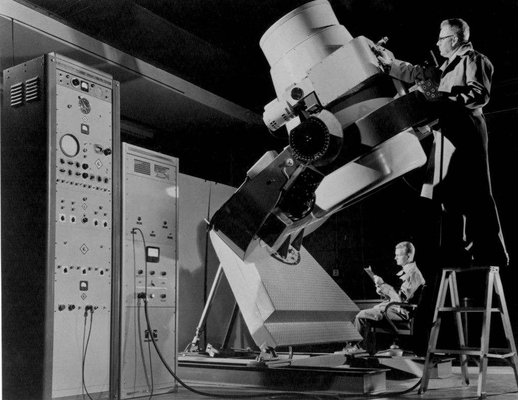
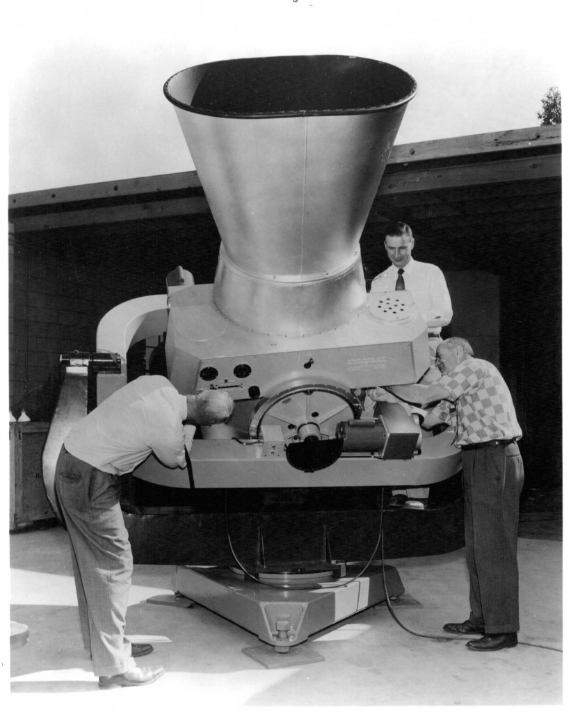
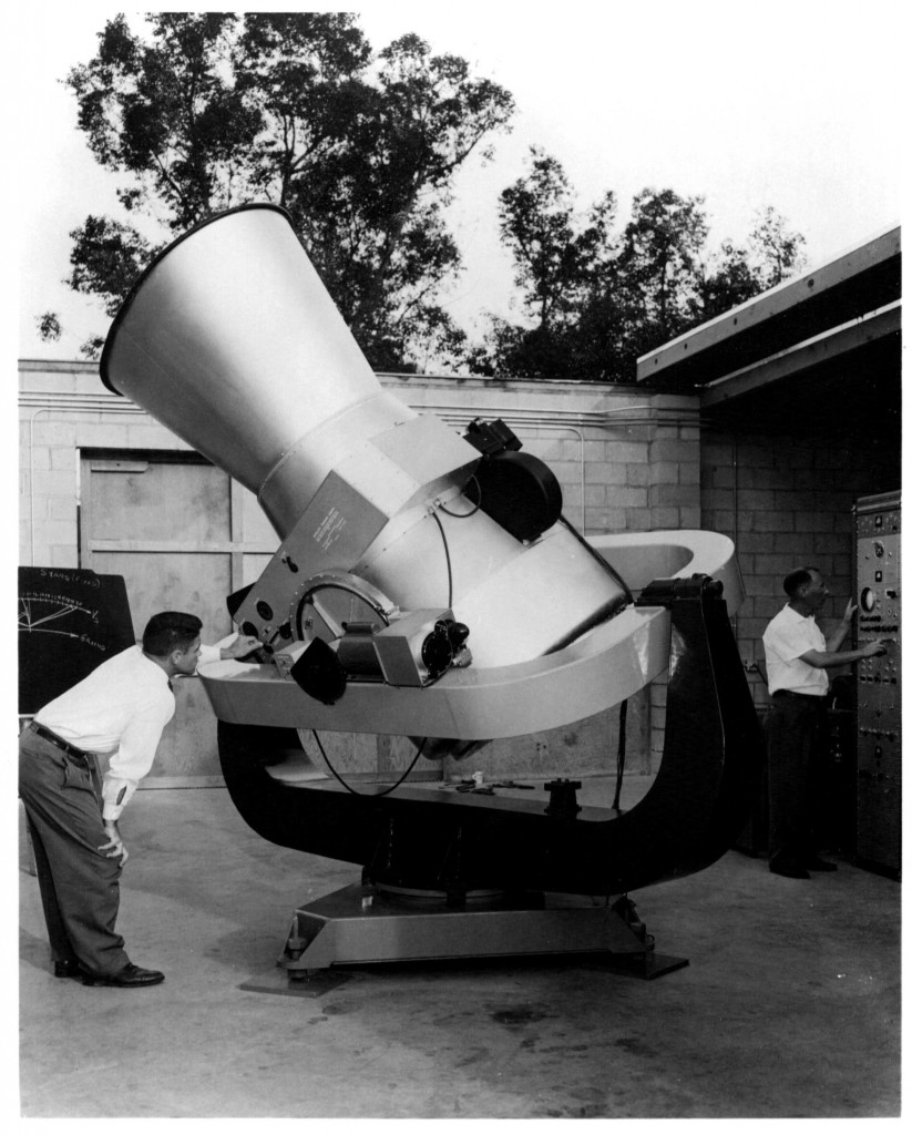
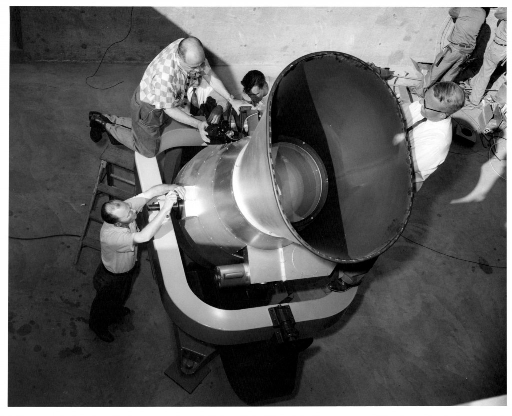
The Baker Nunn Missile Reentry Tracking Camera was designed to have a triangular base.                                      A 150-lb/ft Inland Torque Motor was installed in the base assembly and rotated the fork plus or minus 200 degrees in azimuth rotation.
A 100-lb/ft Inland Torque Motor rotated the gimbal-ring mounted to the fork-tines would rotate the gimbal-ring plus or minus 80 degrees in elevation.
Mounted in the center of the gimbal-ring was the optical camera tube assembly.
The camera assembly could be motor driven plus or minus 70 degrees in a 2nd elevation axis that was 90 degree to the 1st elevation axis.
The total moving mount was balanced such the it could be easily be positioned to track across any missal’s angular reentry direction in the sky

The Optical Configuration
The Baker Nunn Missal Reentry Tracking Cameras consists of a three-element 20-inch entrance aperture corrector lens system.
Mounted on top of the corrector lens assembly is a multi-set of triangular prisms converting the incoming sky image into a spectrum image.
It was thought a spectrum image of the incoming missile would determine which was the real missile and which was decoy chaff that had been released prior to reentry.

The corrected spectral image is then projected down to a 31-inch f/1 spherical primary mirror.
The focusing converging image is then reflected back up to a 4-inch x 6-inch x 0.6-inch thick mosaic of fiber-optics making film supporting focusing plate.

This focusing plate is constructed by bonding together hundreds of small hexagonal fiber optic bundles. It was ground and optically polished on one side to the curved focal plane. The opposite side was optically polished flat.

The imaged projecting up from the primary mirror would focus on the on the curved focal-plane side of the fiber-optics mosaic. This enabled the curved focused image to be transferred thru to the opposite of the fiber optics mosaic.
The emulsion side of the 4-inch wide film would be in contact of the flat side of the fiber-optics mosaic when an exposure is made.
The film is then transported out to a take-up canister stopping with its trailing length ready for the next exposure.

Five different exposure transit speeds were available. The fastest speed was five frames per second. Setting this exposure and transit at five frames per second, the film was entering, stopping for an exposure and exiting at an unbelievable rate of speed.

The Mechanical Operation
Transporting the film was accomplished by blowing an air blast in into the film supply canister.
This air blast would create a 6.25-inch floating loop of film in this supply canister.
To advance the film, a blast of air into the film take-up canister would then pull the film across the film bridge from the supply canister creating a new 6.25-inch replacement floating loop of film in the take-up canister.
This trading air between the two canisters would pull the film across the film bridge. The size of the loop and frequency between the air blasts would establish the length and timing for the proper exposure time.
The film would stop with its trailing length ready for the next exposure.
A stall-torque motor was continually taking up any slack exposed film in the take-up canister. The stall-torque motor would keep the film taught when the exposure was taken.
There was a film back-up plate between the flat side of the fiber-optics mosaic and the back-up plate. There was just enough space between the fiber-optics mosaic surface and the back-up plate for the film to slide freely during its transit and keeping it in focus against the fiber-optics mosaic.

A selectable speed worm and gear drive would drive the camera assembly tracking a satellite passing overhead.
Selectable transporting speeds could be implemented for tracking different satellite transit speeds.
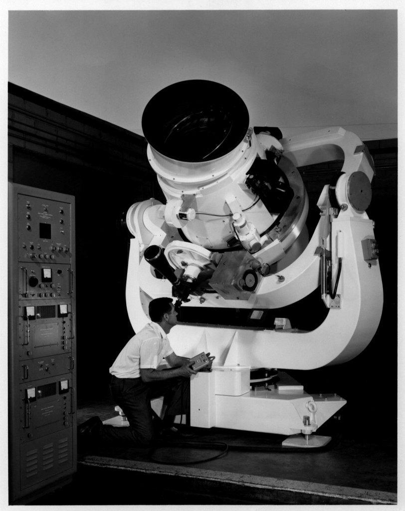
Baker Nunn Kwajalein Slit-less Spectrograph camera for U.S. Air Force.
Boller and Chivens General manager Frank Shafer, operating the camera.

In 1964, the United States initiated its Anti-ballistic missile testing program with the Nike-Zeus program in Kwajalein Atoll. Authorities moved the remaining Marshall Islanders who lived scattered on their land throughout the atoll to the small shantytown of Ebeye, which had been erected, with plywood housing by American contractors.    http://www.nuclearabms.info/NikeZeus.html

At the beginning of each day a boat would ferry Kwajalein islanders over to Kwajalein Atoll to work at the base. At sundown these Kwajalein islanders would be ferried back to the shantytown. No Kwajalein islanders were allowed on the base after sundown because of the mixed gender of all the U. S. citizens residing there

The Baker Nunn Missile Reentry Tracking Camera was installed on Kwajalein Atoll in the South Pacific. The location is approximately 5-degrees north of the equator.
Missiles launched from the Vandenberg, California would pass over the Pacific Missile Range. The missile would enter earth’s atmosphere over the Kwajalein Atoll.
A Nike Zeus missal test launching station was also located on the Kwajalein Atoll adjacent to the Missile Reentry Tracking spectrograph camera.

The purpose of the spectrograph camera was to photograph through spectroscopy photos of the incoming missiles.
The photos would determine what were the differences of a real incoming missile and the decoy chaff traveling along with the missile. The photos had to be taken of the missile well before it reached an incoming altitude of 100,000 feet.

A Nike Zeus missile would be launched programmed to intercept the real incoming missile with information from the spectrograph camera photos.
http://www.nuclearabms.info/NikeZeus.html

The only similarity of the Slit-less Spectrograph camera was the basic Cameras Mount outline and the Dr. James Baker optical design.
The Shutter Assembly, the Film Size, the Film Transport System and the Cameras Mount’s Positioning Mechanics were completely redesigned.

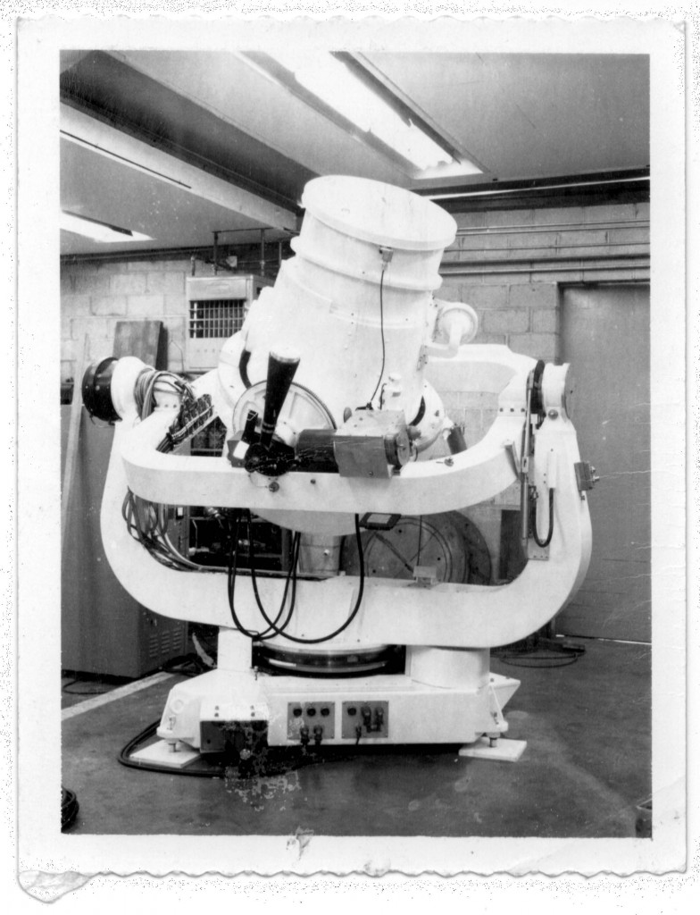
Three Air Force Baker Nunn Satellite Tracking Cameras

The Air Force Baker Nunn Satellite Tracking Cameras were similar to the Smithsonian Satellite Tracking Cameras.

This is the first of three Air Force Baker-Nunn Cameras.
On the left is a Standard Time clock built by Norman Clock Co, Green Bay, Wisconsin

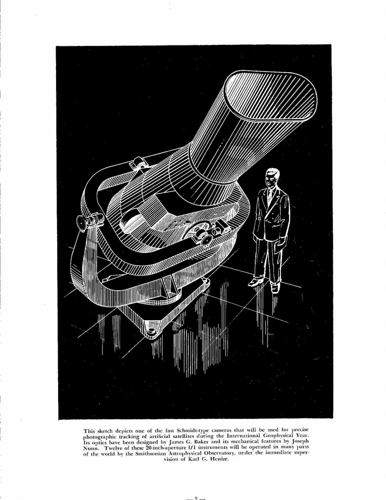
The Baker Nunn Cameras are designed to have a triangular base.  Mounted on the base is a Fork rotating 360 degrees. A Gimbal Ring is mounted to the Fork tines ends that will rotate plus or minus 80 degrees in elevation.
Mounted on the center of the Gimbal Ring is the Optical Camera assembly.
The Optical Camera assembly can be motor driven plus or minus 70 degrees in a 2nd elevation axis that is 90 degree to the 1st elevation axis.
The total moving mount is balanced such the it can be positioned to track across any satellite angular direction in the sky

Both the Azimuth and Elevation rotations are electrically motor-driven.

The satellite camera can be operated in a standard Alta/Azimuth mount.
An alternate condition where the camera mount base rear support can be raised up with a ball screw jack.
This allowed its azimuth axis to be tilted to a polar axis angle where its North/South location is to located on its final installation.
An adjustable tubular column is installed to lock the mount in this angular position.
This angular position allows the camera to place a celestial background photo of stars when a satellite photo was taken.
Both the Azimuth and Elevation rotations are electrically motor-driven.
The satellite camera can be operated in a standard Alta/Azimuth mount.

Mounted on the center of the gimbal ring is the optical camera assembly.
The optical camera assembly can be motor driven plus or minus 70 degrees in a 2nd elevation axis that is 90 degree to the 1st elevation axis.
The total moving mount is balanced such the it can be positioned to track across any angular direction in the sky

The Optical Configuration
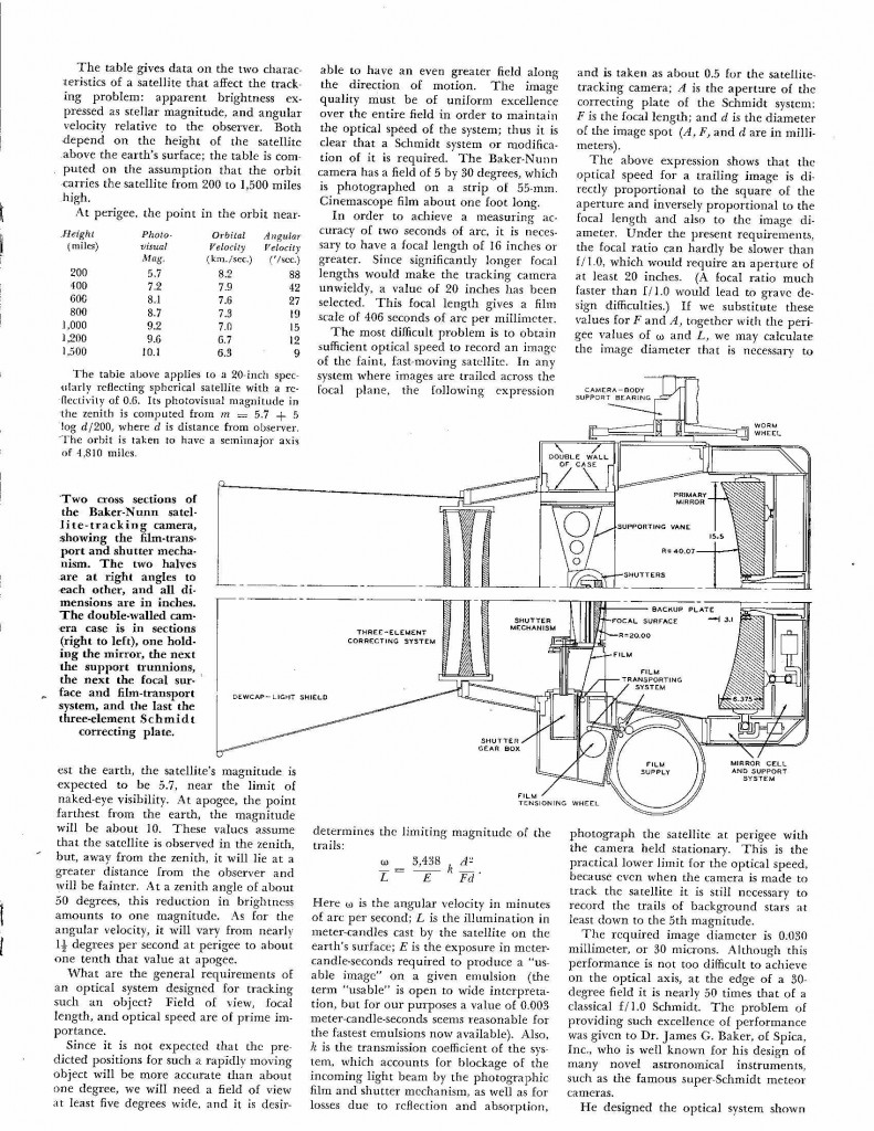
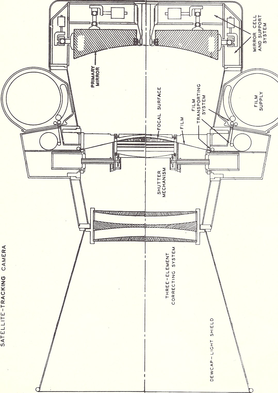
The Baker Nunn Satellite Tracking Cameras consists of a three-element 20-inch entrance aperture corrector lens system.
The corrected image is projected down to a 31-inch f/1 spherical primary mirror.
The focusing converging image is then reflected back up to an optical shaped focusing surfaced back-up plate where the film exposure are made.

The Mechanical Operation
For a satellite photo run with the Baker Nunn camera the following operations occur.
The Satellite Tracking Cameras consists a continuous 35-mm length of film coming from a supply canister.
The film is stopped for an exposure at the center of the film bridge and is then stretched over the optical shaped surface on a backup plate. The stretching of the film will place the emulsion surface of the film in focus over the total width and length of the films exposure.
The film is then transported out to a take-up canister stopping with its trailing length ready for the next exposure.

Continuously, a pair of rotating shutter blades is passing around the film bridge, which will create clear stripes in the exposed image trail of the traveling satellite photo.
Continuously, another complete shutter is opening and closing, is blocking unwanted exposure during the film transport.

A selectable speed worm and gear drive will drive the camera assembly tracking a satellite passing overhead.

Selectable transporting speeds can be implemented for tracking different satellite transit speeds.

Simultaneously an International time signal clock from the Norman Clock Co, Green Bay, Wisconsin is located at each Baker Nunn Satellite Tracking station.
A time signal will be projected on the end of each exposure of the film.

Baker Nunn Satellite Tracking Cameras

Left to right, front Clyde Chivens and Joseph Nunn. Harry Boller is at the rear of the mount.

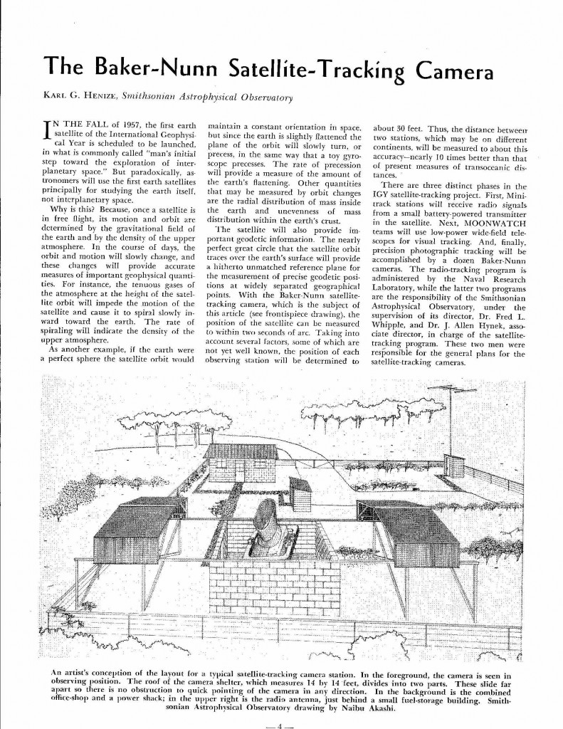
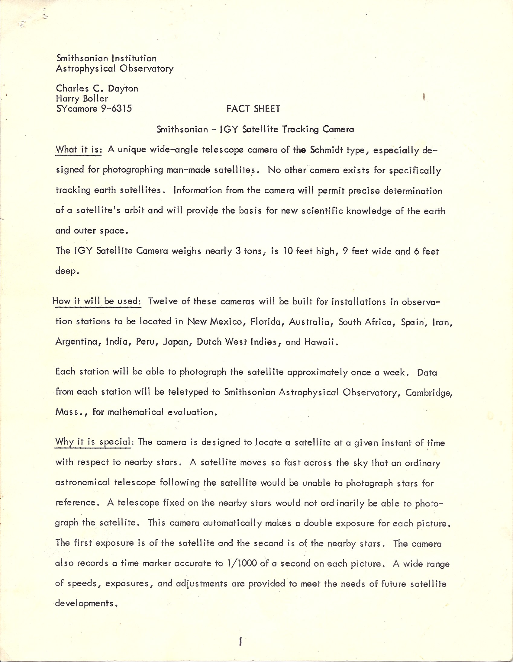
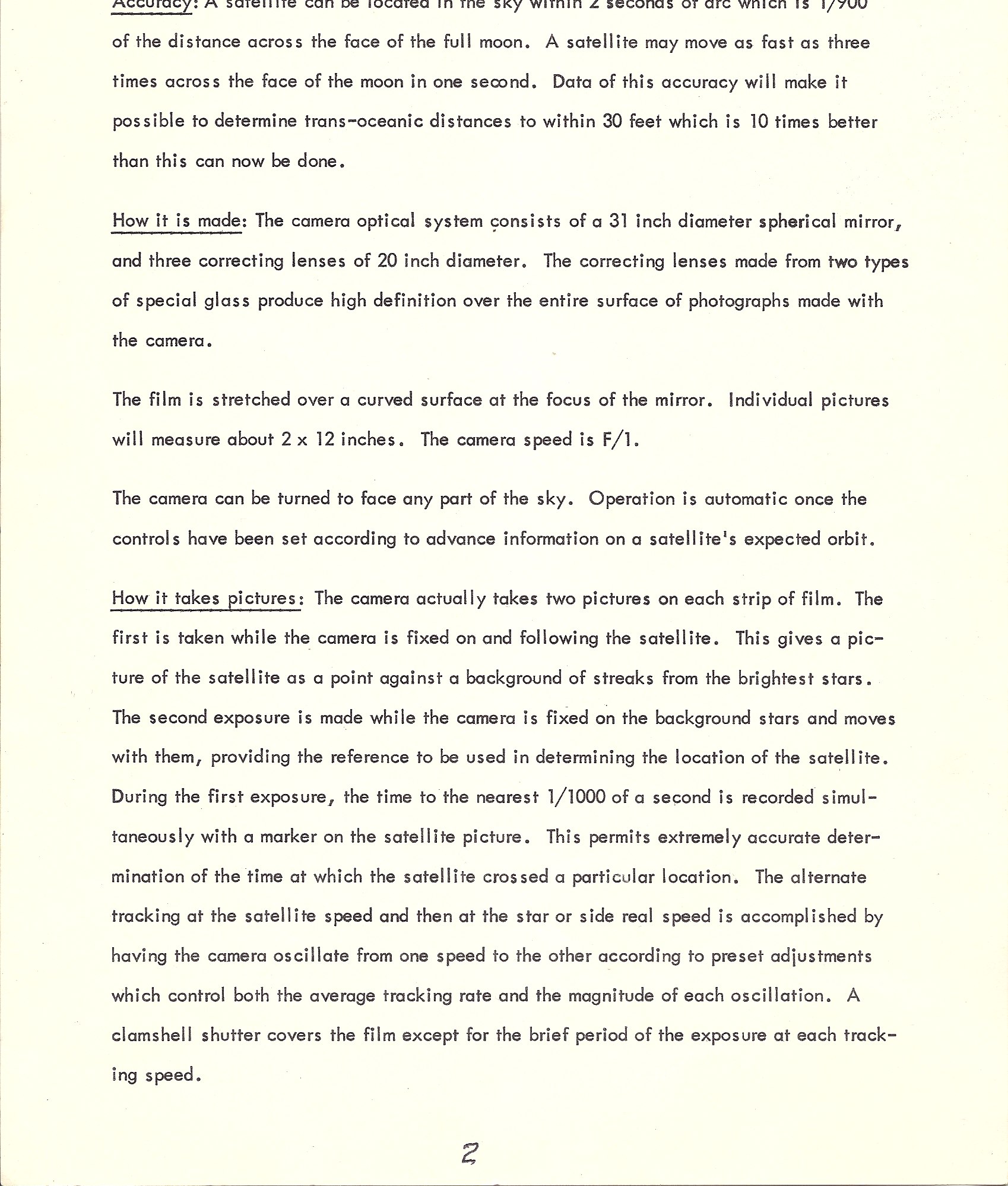
Boller & Chivens manufactured twelve Baker Nunn Schmidt optical camera telescopes for Smithsonian Astrophysical Observatory .
The optical design included a 20-inch, three element corrector lens assembly projecting to a 30” diameter, f/0.75 primary mirror reflecting back to glass aspheric focal plane surface. Ten inches of 55 mm wide cinemascope film was stretched over the focal plane surface for tracking artificial satellites.

The first deliverable Baker-Nunn camera In the foreground, Karl Heinz, the principle investigator for Smithsonian’s part in Satellite Tracking program. Audrey Stinett is in front of the Norman Time Standard clock.

Clockwise, Audrey Stinnet, Smithsonian station personnel training leader. Joe Nunn kneeling on camera support ring. Frank Shaffer, B&C program manager and Clyde Chivens, at front of camera.

The Baker Nunn Cameras are designed to have a triangular base. Mounted on the base is a fork rotating 360 degrees. A gimbal ring is mounted to the fork tines that could rotate plus or minus 80 degrees in elevation. Mounted on the center of the gimbal ring was the Optical Camera assembly. The camera assembly can be motor driven plus or minus 70 degrees in a 2nd elevation axis that is 90 degree to the 1st elevation axis.

The total moving mount is balanced such the it can be positioned to track across any angular direction in the sky.

The Optical Configuration
The Baker Nunn Satellite Tracking Cameras consists of a three-element 20-inch entrance aperture corrector lens system. The corrected image is projected down to a 31-inch f/1 spherical primary mirror. The focusing converging image is then reflected back up to an optical shaped focusing surfaced back-up plate where the film exposures are made.

The Mechanical Operation
For a satellite photo run with the Baker Nunn camera the following operations occur:
The Satellite Tracking Cameras consists of a continuous 35-mm length of film coming from a supply canister. The film is stopped for an exposure at the center of the film bridge and is then stretched over the optical shaped surface on a backup plate. The stretching of the film will place the emulsion surface of the film in focus over the total width and length of the films exposure. The film is then transported out to a take-up canister stopping with its trailing length ready for the next exposure.
Continuously, a pair of rotating shutter blades is passing around the film bridge, which will create clear stripes in the exposed image trail of the traveling satellite photo.
Continuously, another complete shutter is opening and closing, blocking unwanted exposure during the film transport.
A selectable speed worm and gear drive will drive the camera assembly tracking a satellite passing overhead.
Selectable transporting speeds can be implemented for tracking different satellite transit speeds.
Simultaneously an International time signal clock from the Norman Clock Co, Green Bay, Wisconsin is located at each Baker Nunn Satellite Tracking station. A time signal will be projected on the end of each exposure of the film.

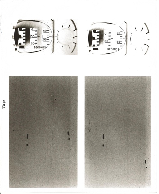
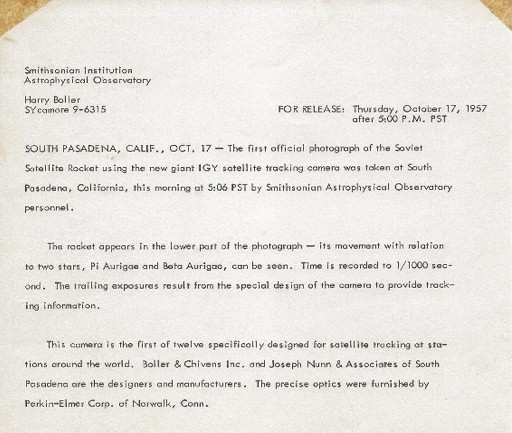
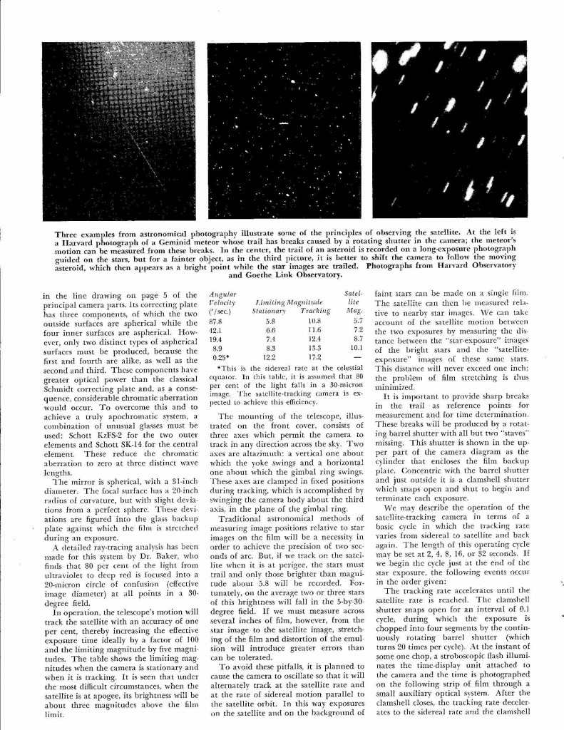
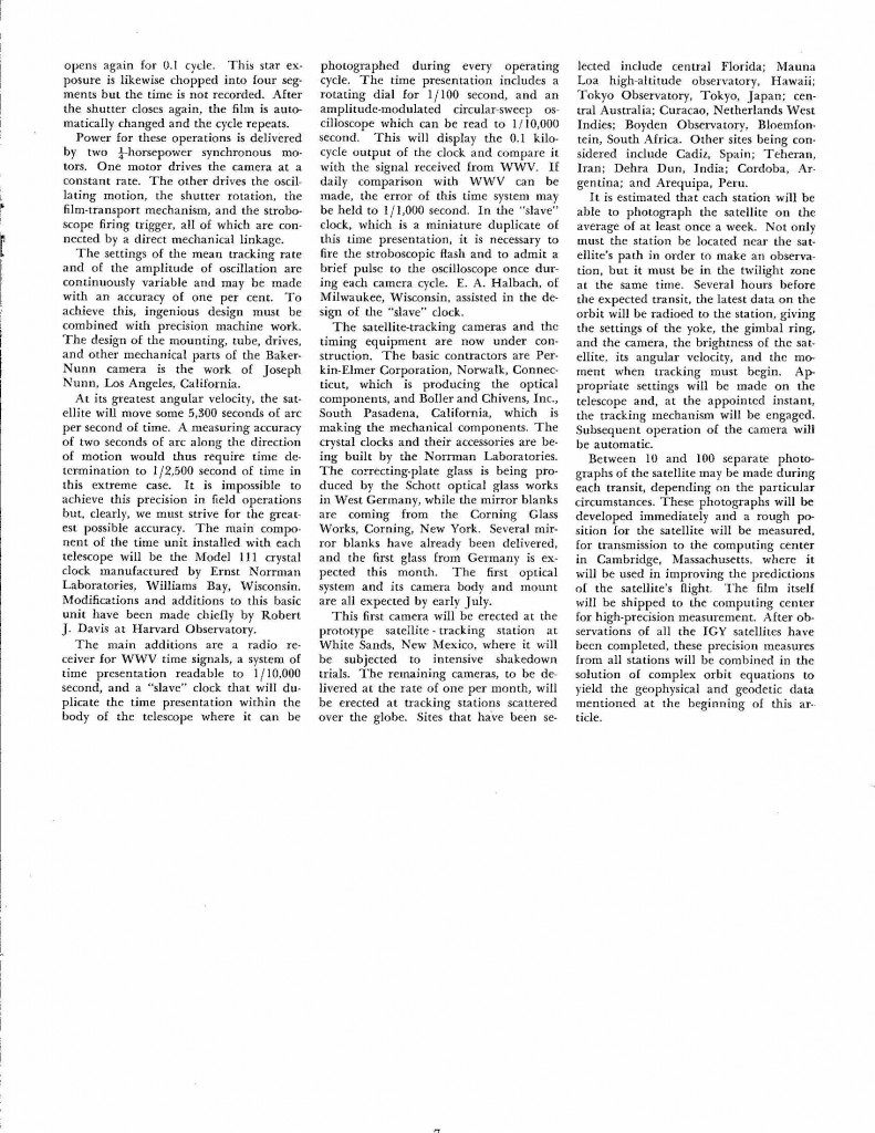
The first photos taken of “Sputnik”, the Soviet Satellite Rocket, with the first of twelve Baker Nunn STRAC satellite tracking cameras as it passed over Boller and Chivens’ assembly building on October 17, 1957.


Click here for additional information about Sputnik and this project.

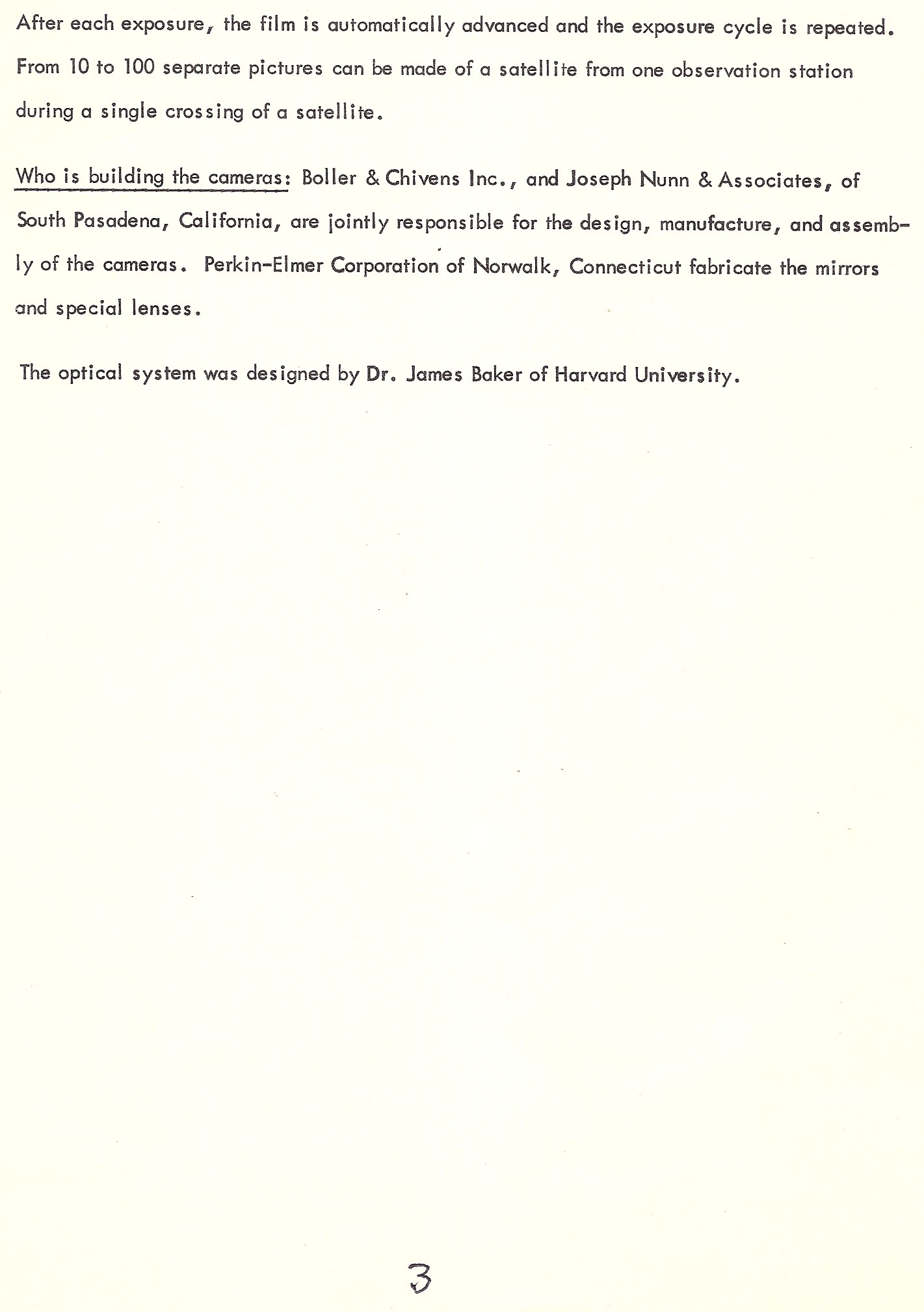
Baker Nunn Satellite Tracking Cameras – Smithsonian Information