 Larry Steimle: Boller and Chivens Optical Test Engineer
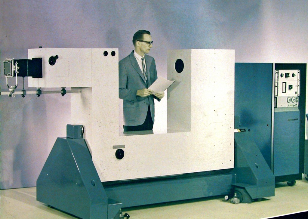
The instrument had two lasers including a giant pulse laser for studying turbine blades.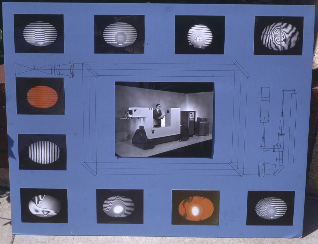
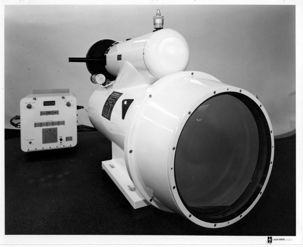
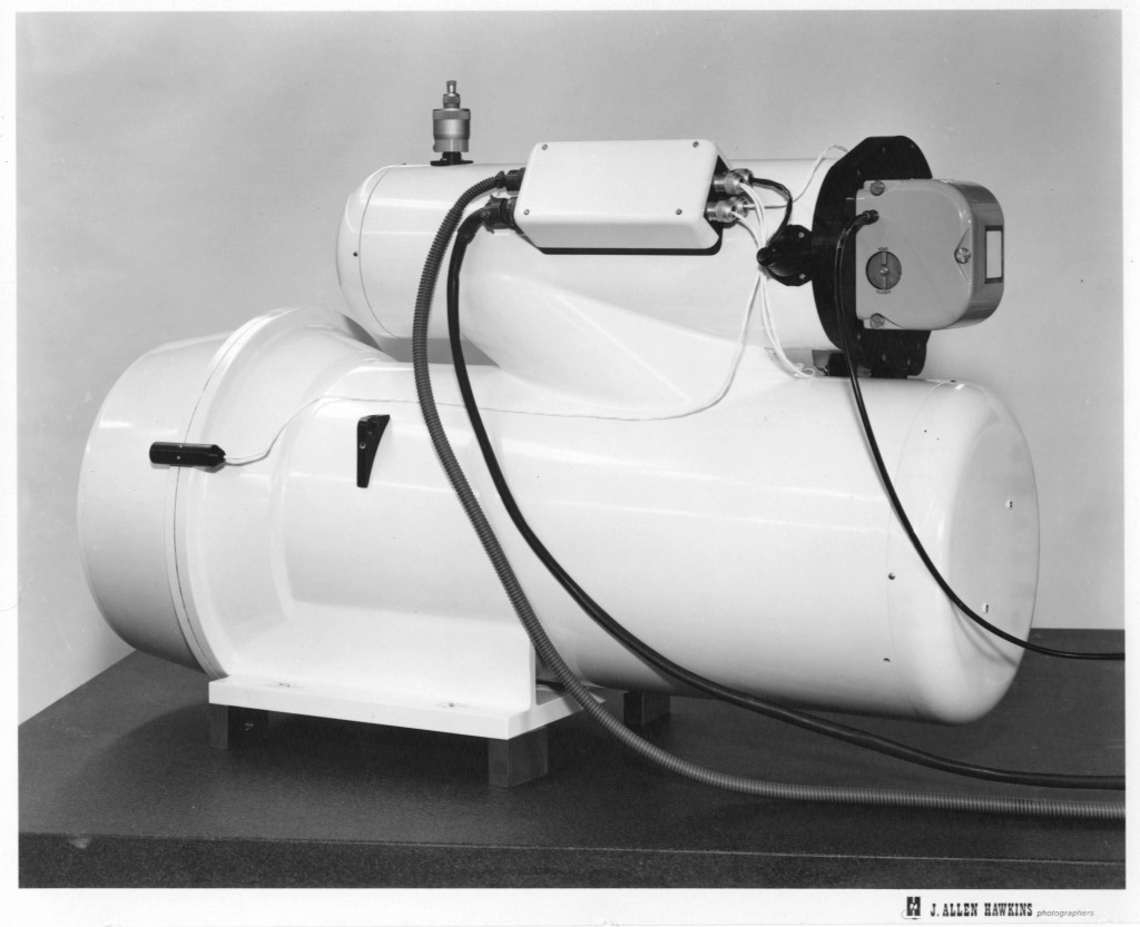
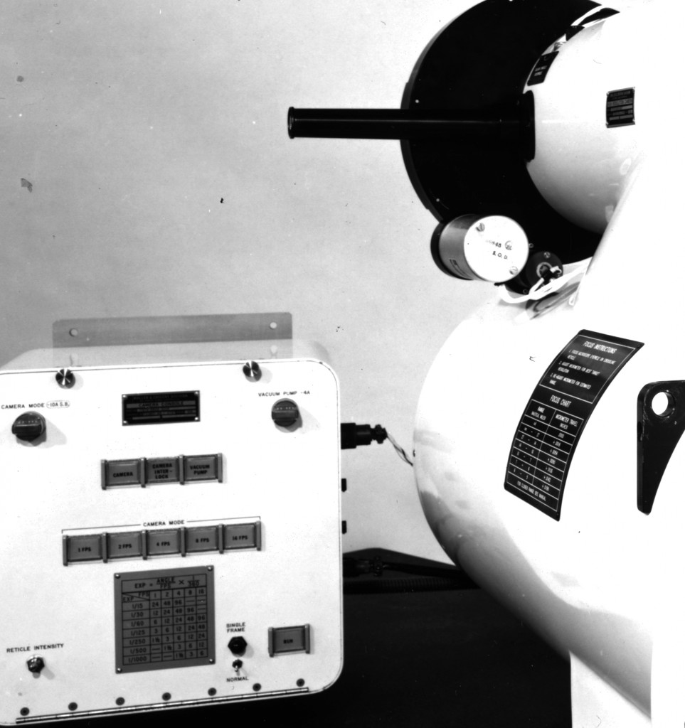
Spectroheliograph for a 60-Inch U.S. Naval Observatory Telescope
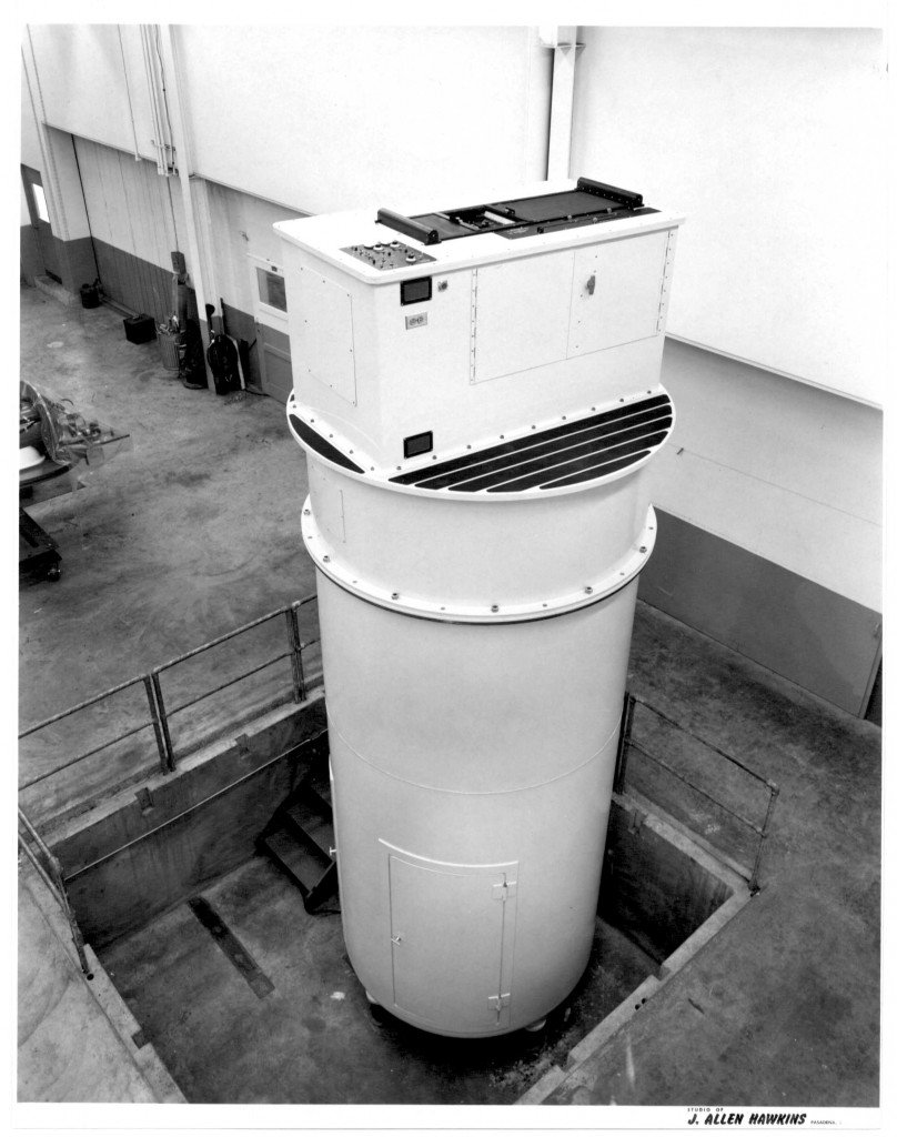 Boller and Chivens designed and manufactured.
Assembled in #2 pit of Boller and Chivens telescope assembly building.
To learn more about Spectroheliographs, visit http://en.wikipedia.org/wiki/Spectroheliograph
Optical Testing Bench
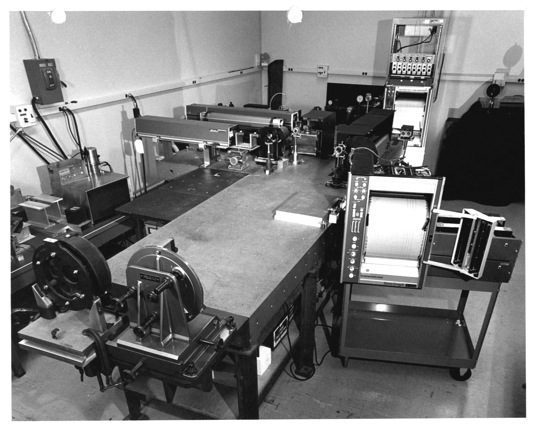
Boller and Chivens assembled optical assembilies for test bench installed at Perkin-Elmer, Pomona, California.
The optical table was used for mounting optical flats for collimation tests in foreground.
Multi-collimator Camera Resolution Tester for Hill Air Force Base
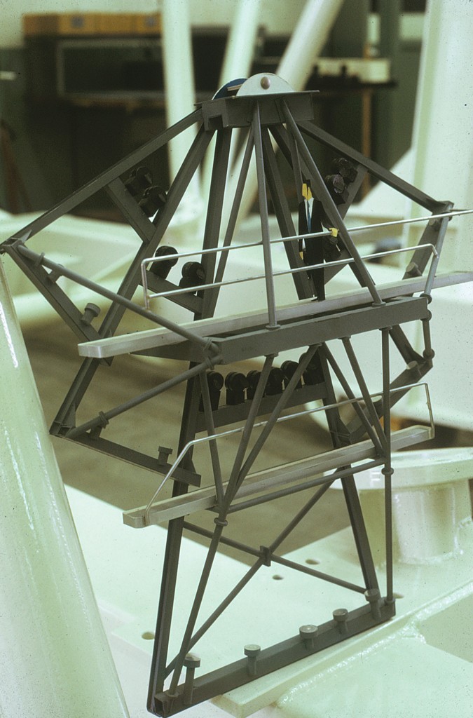 Aerial Camera Resolution Testing Station Model for Concept Proposal
which was designed by John Demaree of Boller and Chivens, manufactured and installed by Boller and Chivens.
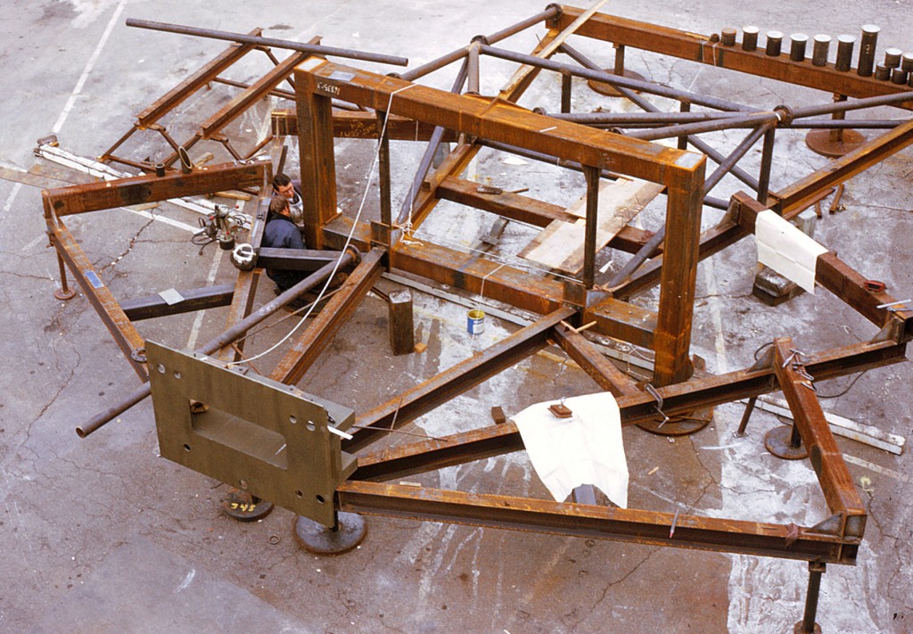 The 30’ high 6-ton steel frame test station being fabricated on its side in the Boller and Chivens parking lot.
The test frame was installed upright in an underground temperature controlled vault.
The entire instrument, essentially a monolithic structure. It is vibration isolated, resting on three air isolation mountings to fixed piers.
Don Winans and Will Harrison of Boller and Chivens made the installation of the structure at Hill Air installed the structure at Hill Air Force Base in Ogden, Utah.
Larry Steimle of Boller and Chivens installed the optics and cameras. Larry completed all the testing requirements.
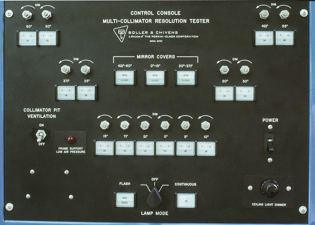 Main control panels depicting the14 collimator array’s tilt angles. No two angles the same.
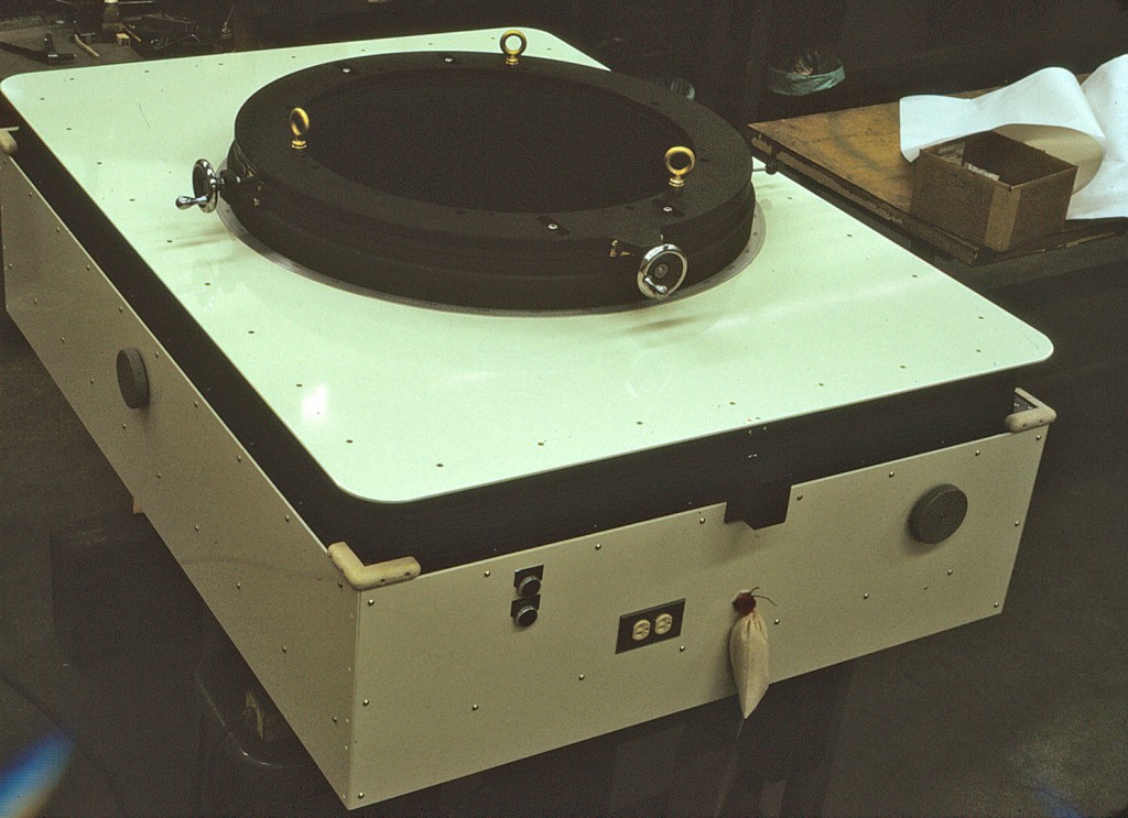 The camera under test could be rotated on the mounting plate and multiple exposures could be taken to get resolution images all across and around the field of the 9 inch photographic plates.
 Target wheel with the standard USAF Resolution target in place. The test table was at the top the frame at ground level.
Aerial cameras would be mounted on top of a custom rotary table coupled with x-x and y-y adjustments. A center target wheel allowed easy changing. Each target had its own special light source vented outside to prevent heat induced air distortions.
A chain drive was part of the focusing system.
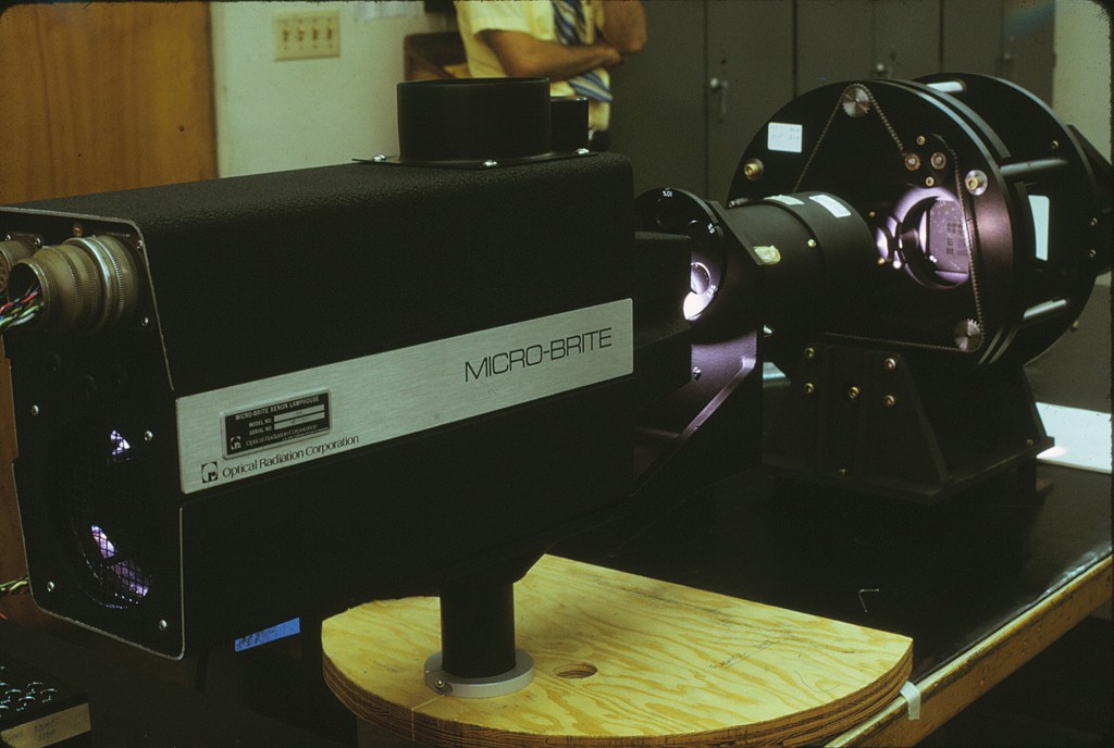 Resolution Test Light Source and Target Assembly
A high intensity light source projecting into the rear of the target wheel.
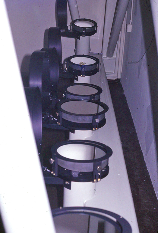 At the bottom of the frame was an array of 14 off-axis parabolic collimating mirrors from 12 inches in diameter down to 6 inches.
All collimator mirrors are precision off-axis parabolas.
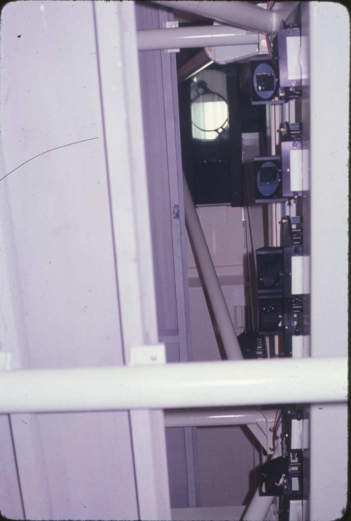 Looking up from just above the collimating mirrors to the folding mirrors and the target assemblies.
Test Frame for Forward Looking Radar Devices
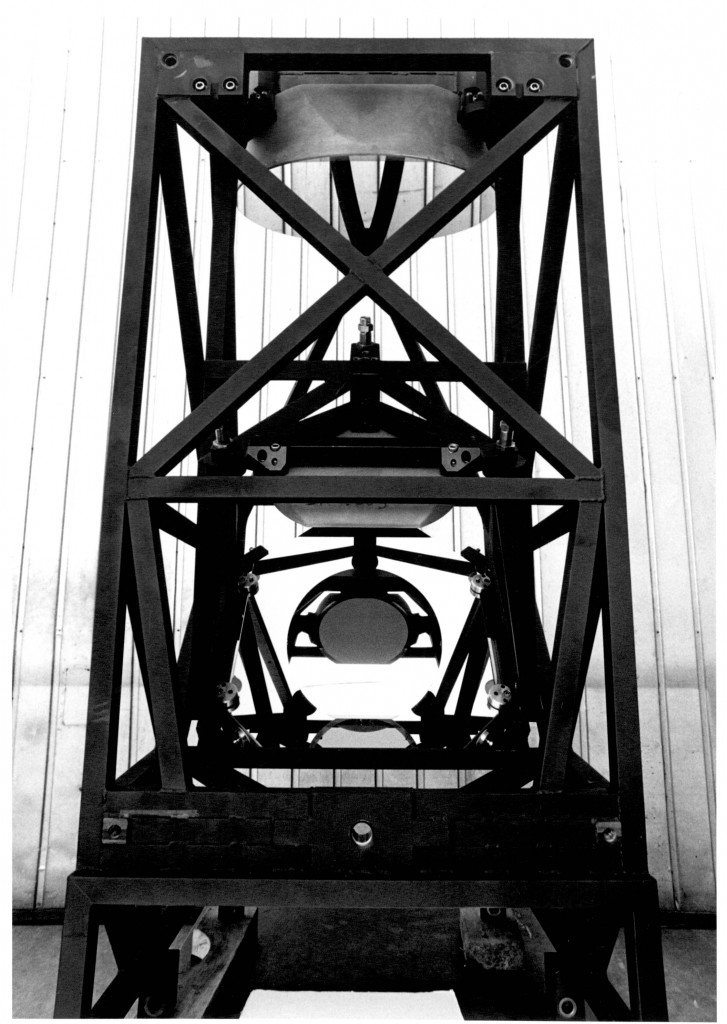 Designed and manufactured by Boller and Chivens
Ten test frames were constructed from 1” square Invar tubing for temperature stability.
A Forward Looking Radar device was placed horizontally in front of the test platform.
A beam of information was projected filling to an optical flat. The beam reflected by this 1st flat mirror, continues to expand and is reflected again by a 2nd larger flat mirror. The beam continues to expand to a 16 inch diameter off- axis parabolic mirror. This mirror collimates the expanded beam for testing Forward Looking Radar devices. All mirrors were contained in custom three point non-restraining mirror mountings.
Facet Eye Camera for Missile Tracking for U.S. Army Engineers
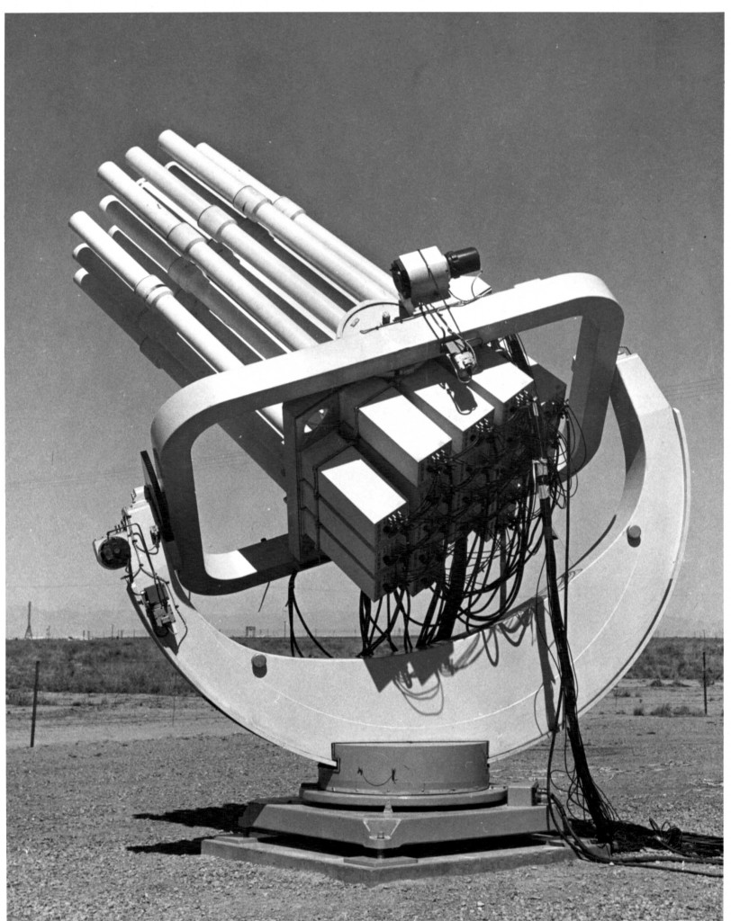 A Joe Nunn design with Boller and Chivens manufacturing with multi TV cameras.
Mechanical Azimuth and Elevation positioned the TV camera mount.
The multi-cameras rectangular support ring was motor driven to monitor track launched missile objects. Twenty-five television cameras mounted together would track the launched missiles.

